6 installing the communications modules – Yaskawa MEMOCON GL120 User Manual
Page 396

!
!
!
5.2 Installing Mounting Bases and Modules
— 5-39 —
5.2.6 Installing the Communications Modules
1) This section shows how to install and remove the following Communications
Module.
(1) Remote I/O Drive Module
(2) Remote I/O Receiver Module
(3) 2000-Series Remote I/O Driver Module
(4) MEMOBUS Module (RS-232)
(5) MEMOBUS Module (RS-422)
(6) PC Link Module
(7) Uniwire Interface Module
(8) Uniwire H-System Interface Module
(9) Distributed I/O Driver Module
(10) YENET 1600-D Module
(11) Ethernet Interface Module
(12) Optical/Electrical Conversion Module
Note
See 5.2.4 Installing the Terminal Block Field Connection Module for M-NET Modules instal-
ling and removing.
2) Installing modules
Caution
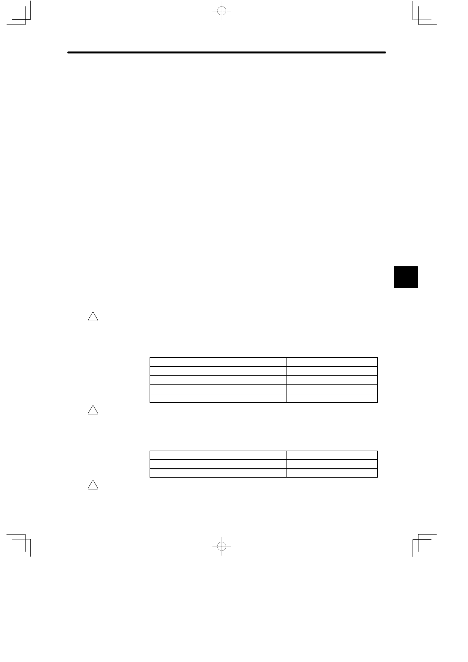
Mount the Modules mentioned in the table below on CPU racks (racks with CPU Modules).
Mounting these Modules on any other racks may damage the Modules or cause a mal-
function of the GL120 and GL130.
Modules to be Mounted on CPU Rack
Model No.
Remote I/O Driver Module
JAMSC-120CDR13100
2000-series Remote I/O Driver Module
JAMSC-120CDR13110
PC Link Module
JAMSC-120NFB23100
Ethernet Interface Module
JAMSC-120NET12100
Caution
Mount the Modules mentioned in the table below on local channel racks.
Mounting these Modules on remote channel racks may damage the Modules or cause a
malfunction of the GL120 and GL130.
Modules to be Mounted on Local Channel Rack
Model No.
MEMOBUS Module (RS-232)
JAMSC-120NOM13100
MEMOBUS Module(RS-422)
JAMSC-120NOM13110
Caution
When installing the Modules that do not support hot swapping, turn OFF the power supply to
Power Supply Modules.
5
