Yaskawa MEMOCON GL120 User Manual
Page 335
4.8
Other Module
— 4-279 —
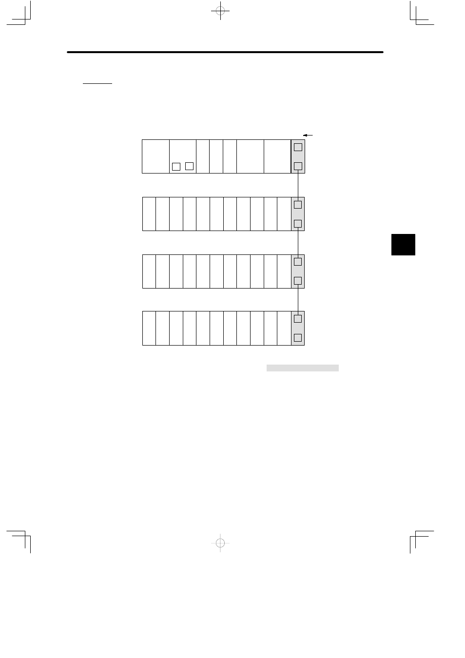
(2) Normally, the Expander Module is mounted to the right end of the Mounting Base,
as shown in the following example:
Example
PS10:
Power Supply Module (7A)
PS05:
Power Supply Module (3A)
CPU30:
CPU Module (32 KW)
DI:
12/24-VDC 16-point Input Module
DO:
12/24-VDC 16-point Output Module
MC20:
4-axis Motion Module
EXP:
Expander Module
MB12:
12-slot Mounting Base
W0100-02:Rack-to-rack I/O Cable (0.2m)
DI
EXP
DI
PS
05
EXP
PS10
DO
DI
M
P
MB12
Slot No.
W0100-02
MC20
MC20
Rack 2
Rack 1 (CPU Rack)
DI
DI
DI
DI
DI
DI
DI
DI
DI
MB12
CPU30
1
2
3
4
5
6
7
8
9
10
11
12
1
2
3
4
5
6
7
8
9
10
11
12
EXP
DI
PS
05
W0100-02
Rack 3
DI
DI
DI
DI
DI
DI
DI
DI
DI
MB12
1
2
3
4
5
6
7
8
9
10
11
12
EXP
DO
PS
05
W0100-02
Rack 4
DO DO DO DO DO DO DO DO DO
MB12
1
2
3
4
5
6
7
8
9
10
11
12
Figure 4.84 Mounting Expander Modules
c) Rack-to-rack I/O Cable Connectors
(1) Rack-to-rack I/O cable connectors are used to connect two adjacent Expander
Modules using Rack-to-rack I/O Cable. There are 2 connectors: 1CN and 2CN,
and they have the same functions. There is no distinction between input and out-
put.
4
A
EXAMPLE
"