Yaskawa MEMOCON GL120 User Manual
Page 150
System Components: Functions and Specifications
4.3.6 Using CPU Modules 3 (For CPU10) cont.
— 4-94 —
Table 4.35 Memory Protection Settings
Position
Name
Function
Right
PRT
Setting the toggle switch to the right turns ON memory protection
for the CPU10 Module. With this setting, none of the following
operations can be performed from a programming device
(Programming Panel or personal computer) connected to a
communications port.
1) Inputting or changing the user program
2) Loading data
3) Manipulating coils or relays
4) Changing reference data (e.g., holding registers)
Center
NOM
Setting the toggle switch to the center or left turns OFF memory
protection for the CPU10 Module. With this setting, all of the
Left
RUN
protection for the CPU10 Module. With this setting, all of the
operations disabled by turning ON memory protection can be
performed.
b) RUN Operation
(1) The RUN position is used to change the CPU10 Module from STOP mode to RUN
mode. The CPU10 Module will change from STOP mode to RUN mode when the
key switch is set as follows: Center, then left, and then back to center.
(2) When the CPU10 Module is in RUN mode, operating the toggle switch will not
change the CPU10 Module back to STOP mode.
(3) RUN operation can also be entered by using a programming device, such as a
Programming Panel or personal computer. Refer to the following manuals for op-
eration methods:
• MEMOCON GL120, GL130 MEMOSOFT for P120 Programming Panel User’s Manual
(SIEZ-C825-60.7)
• MEMOCON GL120, GL130 MEMOSOFT for Windows User’s Manual
(SIEZ-C825-60.25)
• MEMOCON GL120, GL130 MEMOSOFT User’s Manual (SIEZ-C825-60.10)
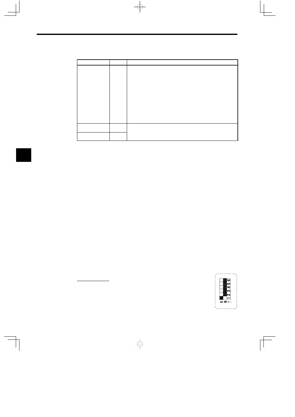
4. DIP Switch
1) The DIP switch consists of 6 pins. The pins are numbered from 1 to 6,
as shown in the diagram on the right.
2) Each pin turns ON when it is moved to the left (toward the toggle
switch).
4