Yaskawa MEMOCON GL120 User Manual
Page 125
4.3 CPU Modules
— 4-69 —
Example 2
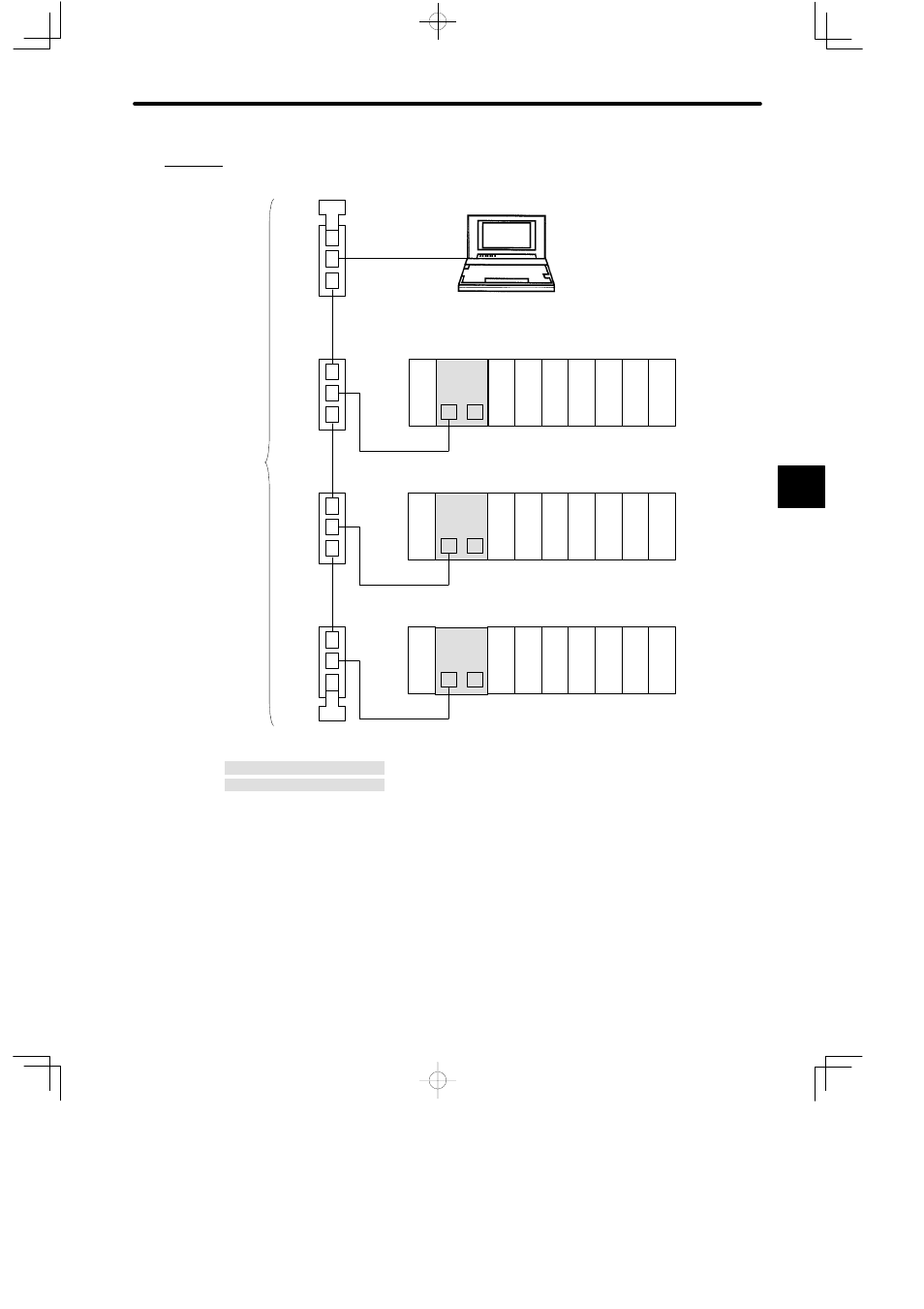
Connecting Programming Panel, GL120, and GL130
M
P
DI
PS
05
Rack 1
(CPU Rack)
DI
DI
DI
DO DO DO
MB10
CPU20
W0803-02
Node address 2
M: MEMOBUS port
P: MEMOBUS PLUS port
P120CN Programming Panel
(with a SA85 Network Adapter)
Node address 1
R
HUB
HUB
W0801-02
W0802-15
M
P
DI
PS
05
Rack 1
(CPU Rack)
DI
DI
DI
DO DO DO
MB10
Node address 3
HUB
W0801-02
M
P
DI
PS
05
Rack 1
(CPU Rack)
DI
DI
DI
DO DO DO
MB10
CPU30
Node address 4
HUB
W0801-02
W0802-15
W0802-15
R
MEMOBUS PLUS
Network
PS05:
Power Supply Module (3 A)
CPU20:
CPU Module (16 KW)
CPU30:
CPU Module (32 KW)
DI:
12/24-VDC 16-point Input Module
DO:
12/24-VDC 16-point Output Module
MB10:
10-slot Mounting Base
HUB:
MEMOBUS PLUS Hub Module
R:
MEMOBUS PLUS Terminator
W0801-02:MEMOBUS PLUS Branch Line Cable (2.0 m)
W0802-15:MEMOBUS PLUS Trunk Line Cable (15.0 m)
W0803-02:MEMOBUS PLUS Branch Line Cable (2.0 m)
CPU30
Figure 4.16 Connecting Programming Panel, GL120, and GL130
4
A
EXAMPLE
"