Yaskawa MEMOCON GL120 User Manual
Page 85
4.3 CPU Modules
— 4-29 —
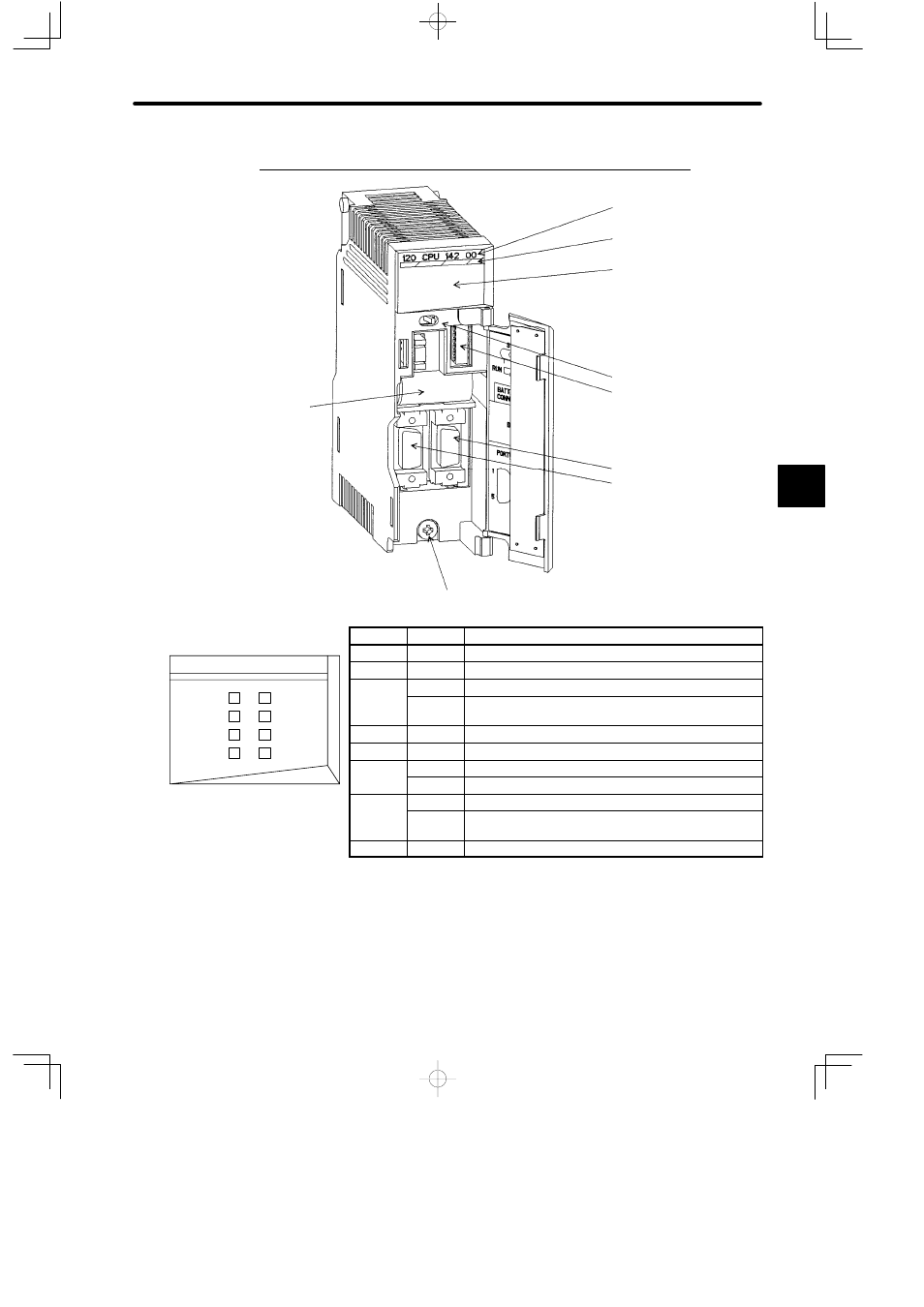
5. Appearance of CPU10 (Model No. DDSCR-120CPU14200)
Module description
(120CPU14200)
DIP switch
Color code (yellow)
LED area
MEMOBUS port 2
Toggle switch
MEMOBUS port 1
Module mounting screw (Use M4 Phillips screwdriver.)
Built-in battery
LED
Color
Indication when ON
READY
Green
CPU Module is normal.
RUN
Green
CPU Module is running.
TX1/ER1 Green
MEMOBUS port 1 is transmitting data normally.
/
Red
Transmission/reception error has occurred on
MEMOBUS port 1.
RX1
Green
MEMOBUS port 1 is receiving data normally.
ACTIVE
Green
The CPU Module can access other Modules.
PRT/BAT Green
The toggle switch is set to ON to protect memory.
/
Red
Voltage in the built-in battery in CPU Module is dropping.
TX2/ER2 Green
MEMOBUS port 2 is transmitting data normally.
/
Red
Transmission/reception error has occurred on
MEMOBUS port 2.
RX2
Green
MEMOBUS port 2 is receiving data normally.
Figure 4.12 Appearance of CPU10
Note
Make sure to replace the battery in the CPU10 Module within two weeks after the PRT/BAT
indicator lights red (replacement battery: BR-2/3A-1).
Programs or data stored in the CPU10 Module or Motion Modules will be lost if replacement is
delayed.
4
RUN
READY
120 CPU 142 00
TX1/ER1
RX1
ACTIVE
PRT/BAT
TX2/ER2
RX2
LED area