Yaskawa MEMOCON GL120 User Manual
Page 172
System Components: Functions and Specifications
4.4.3 Remote I/O Receiver Module cont.
— 4-116 —
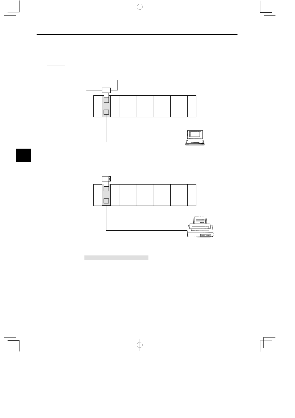
f) An example using the MEMOBUS port is shown below:
Example 1
Connecting Programming Panel to MEMOBUS port
(set on slave port)
Communications by MEMOBUS protocol
DI
PS
05
DI
DI
DI
DI
DI
DO
MB12
Remote channel 1, station 2
DO DO DO
RRC
M
T
T
C
Rack 1 (Receiver Rack)
W0203-03
P120C Programming Panel
M: MEMOBUS port (set slave port)
Example 2
Connecting serial printer to MEMOBUS port
PS05:
Power Supply Module (3 A)
RRC:
Remote I/O Receiver Module
DI:
12/24-VDC 16-point Input Module
DO:
12/24-VDC 16-point Output Module
MB12:
12-slot Mounting Base
W0203-03:MEMOBUS Cable (2.5 m)
M: MEMOBUS port (set combined master/slave port in transparent mode)
Rack 1 (Receiver
Rack)
DI
PS
05
DI
DI
DI
DI
DI
DO
MB12
DO DO DO
RRC
M
T
C
DO
Communications by COMR instructions
Serial printer
(needs to be equipped
with RS-232CI/F)
Remote channel 1, station 3
R
Figure 4.27 Using the MEMOBUS Port
4
A
EXAMPLE
"