Yaskawa MEMOCON GL120 User Manual
Page 146

System Components: Functions and Specifications
4.3.6 Using CPU Modules 3 (For CPU10) cont.
— 4-90 —
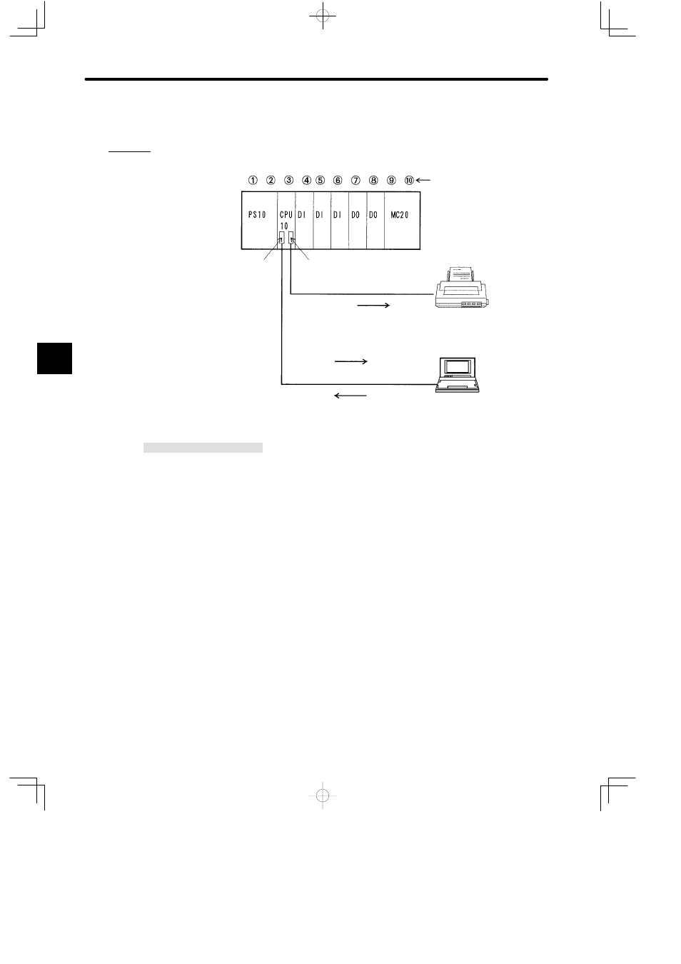
3) Examples of using the MEMOBUS ports are provided below.
a) Connecting Port 2 to an ASCII Device: Printer
Local channel
Rack 1 (CPU Rack)
MB10
W0203-03 cable
P120C Programming
Panel
Slot No.
Port 2
Port 1
Communications via
COMM instruction
Data output
Monitor information
Programming information
Communications via
MEMOBUS protocol
Serial printer with
RS-232C interface
Note Set MEMOBUS port 2
as a master port and to
Transparent Mode.
PS10:
Power Supply Module (7 A)
CPU10: CPU10 Module (8 KW)
MB10:
10-slot Mounting Base
MC20:
Four-axis Motion Module
DI:
12/24 VDC 16-point Input Module
DO:
12/24 VDC 16-point Output Module
W0203-03: MEMOBUS cable (2.5 m)
W0221-03: MEMOBUS cable (3.0 m)
Figure 4.21 Application Examples for MEMOBUS Ports: Printer
4
A
EXAMPLE
"
