202 — 4. using ethernet interface modules – Yaskawa MEMOCON GL120 User Manual
Page 258
System Components: Functions and Specifications
4.4.13 Ethernet Interface Module cont.
— 4-202 —
4. Using Ethernet Interface Modules
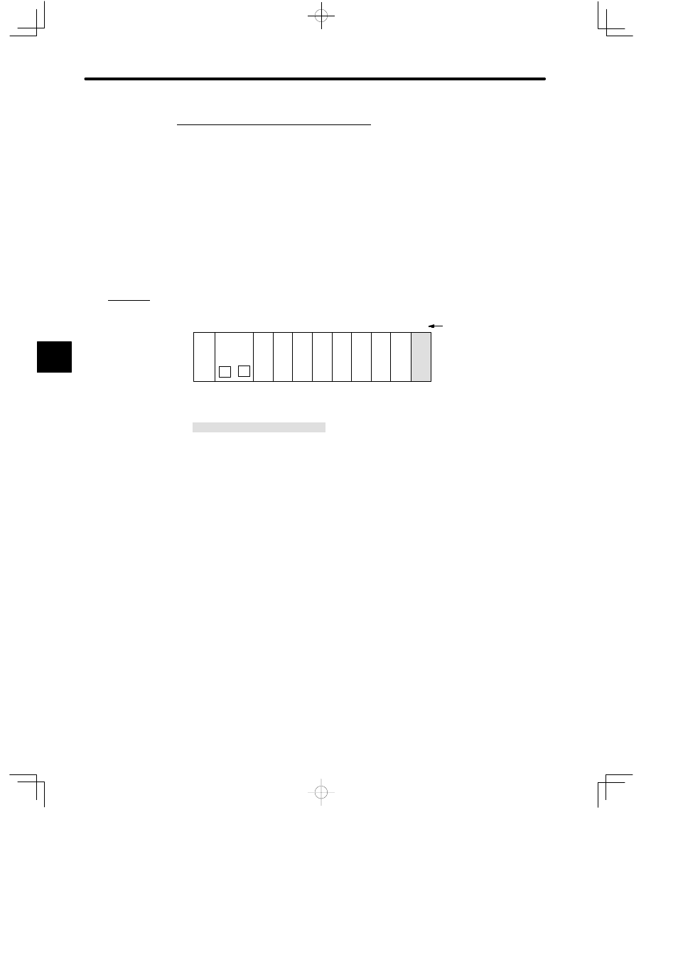
1) Number of Modules
One Ethernet Interface Module can be used.
2) Installation Location
a) An Ethernet Interface Module can be mounted to any slot on the Mounting Base of
Rack 1 (CPU Rack) of the local channel. It will occupy one slot.
b) A mounting example of Ethernet Interface Modules is shown below.
PS05:
Power Supply Module (3 A)
CPU20:
CPU Module (16 KW)
EIF:
Ethernet Interface Unit
DI:
12/24-VDC 16-point Input Module
DO:
12/24-VDC 16-point Output Module
MB12:
12-slot Mounting Base
DI
PS
05
DO
DI
M
P
MB12
Slot No.
Rack 1 (CPU Rack)
CPU20
1
2
3
4
5
6
7
8
9
10
11
12
DO
Local channel
DI
EIF
DO DO DO
Figure 4.61 Connection Example of Ethernet Interface Unit
4
A
EXAMPLE
"