Yaskawa MEMOCON GL120 User Manual
Page 299
4.6 Special Purpose Modules
— 4-243 —
4. Using Pulse Catch Modules
1) Number of Modules
a) The following I/O references are necessary in the CPU Module for each Pulse Catch
and Counter Module.
• 16 consecutive input relays (Not needed if the pulse catch function is not used.)
• 17 consecutive input registers (Not needed if the counter function is not used.)
• 2 consecutive output registers (One set if count clear is not used.)
b) Therefore, the number of Pulse Catch and Counter Modules that can be used is deter-
mined by how many of the above I/O references are available in the CPU Module.
2) Installation Locations
a) A Pulse Catch Module can be mounted to any slot of the Mounting Base of any Rack.
It will occupy on slot.
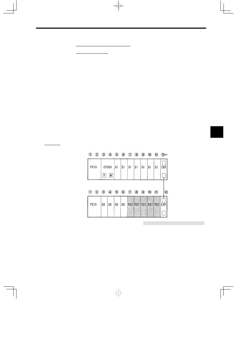
b) The following diagram shows where to mount a Pulse Catch Module.
PS10:
Power Supply Module (7 A)
CPU30:
CPU Module (32 KW)
DI:
12/24-VDC 16-point Input Module
DO:
12/24-VDC 16-point Output Module
PCT:
Pulse Catch and Counter Module
EXP:
Expander Module
MB12:
12-slot Mounting Base
W0100-02:Rack-to-rack I/O Cable (0.2 m)
MB12
W0100-02
MB12
Local channel
Rack 1 (CPU Rack)
Slot No.
Rack 2
Note
The Pulse Catch and Counter Module can be mounted in any slot of any rack although there
may be some system configuration restrictions. Refer to the related documentation for more
details on the restrictions.
Figure 4.73 Mounting Pulse Catch Modules
4
A
EXAMPLE
"