Yaskawa MEMOCON GL120 User Manual
Page 271
4.4 Communications Modules
— 4-215 —
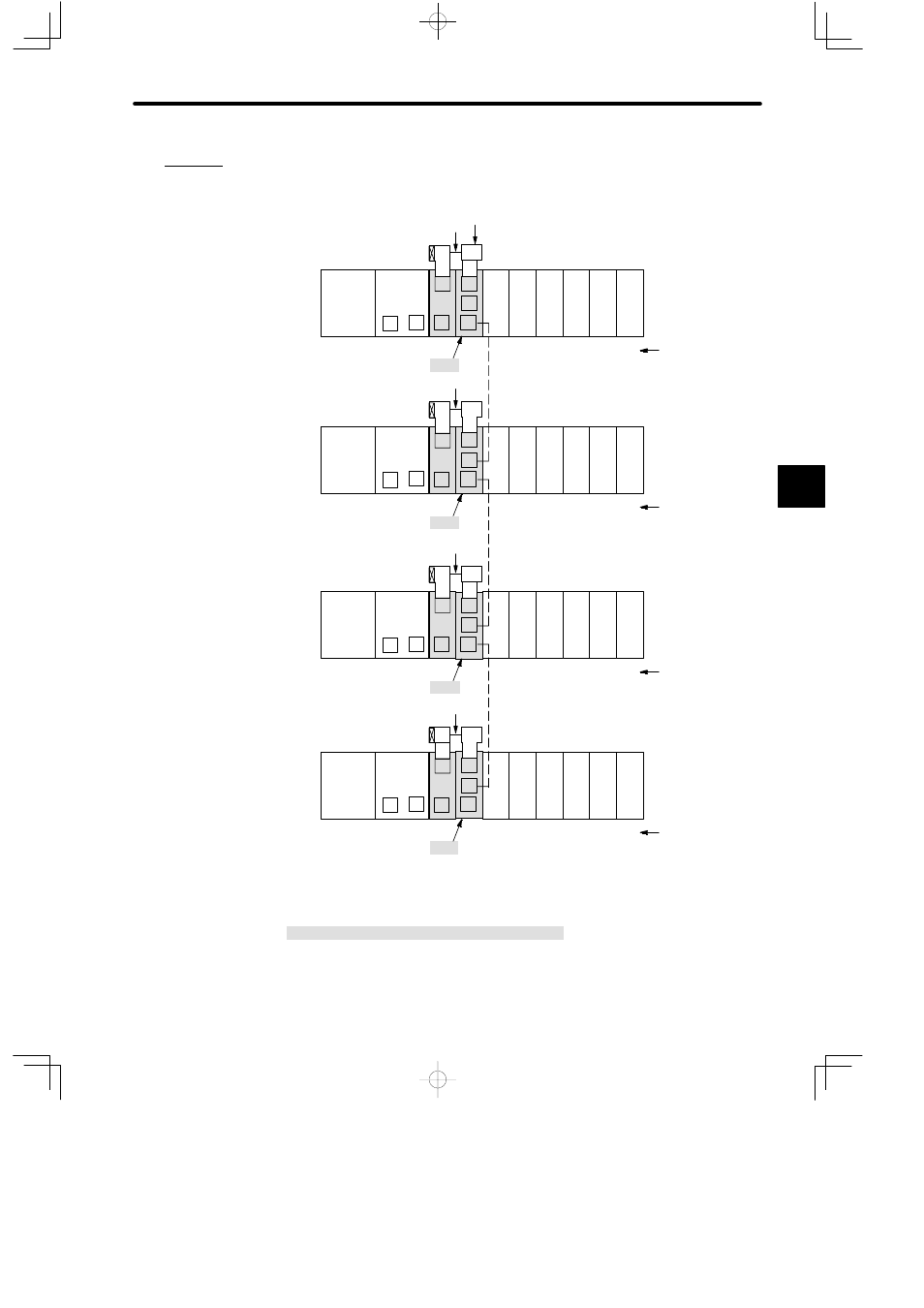
Example
Connecting Optical/Electrical Conversion Modules to PC Link Modules
PS10:
Power Supply Module (7 A)
CPU20: CPU Module (16 KW)
CPU30: CPU Module (32 KW)
LNC:
PC Link Module
O/E: O/E Conversion Module
M
DI
LNC
PS10
DI
DI
P
MB12
Slot No.
Rack 1 (CPU Rack)
CPU30
1
2
3
4
5
7
8
9
10
11
T-adapter
R (Terminator)
PC Link channel, station 1
*1
*2
T
C
DO DO
Local channel
M
6
T
1
3
2
12
DO
Branch line coaxial cable*1
M
DI
LNC
PS10
DI
DI
P
MB12
Slot No.
Rack 1 (CPU Rack)
CPU20
1
2
3
4
5
7
8
9
10
11
R (Terminator)
PC Link channel, station 2
T
C
DO DO
Local channel
M
6
T
1
3
2
12
DO
Optical fiber cable *2
O/E
O/E
*1
M
DI
LNC
PS10
DI
DI
P
MB12
Slot No.
Rack 1 (CPU Rack)
CPU30
1
2
3
4
5
7
8
9
10
11
R (Terminator)
PC Link channel, station 3
T
C
DO DO
Local channel
M
6
T
1
3
2
12
DO
O/E
*2
*1
M
DI
LNC
PS10
DI
DI
P
MB12
Slot No.
Rack 1 (CPU Rack)
CPU20
1
2
3
4
5
7
8
9
10
11
R (Terminator)
PC Link channel, station 32
T
C
DO DO
Local channel
M
6
T
1
3
2
12
DO
O/E
DI:
12/24-VDC 16-point Input Module
DO:
12/24-VDC 16-point Output Module
MB12:
12-slot Mounting Base
Figure 4.63 Connection Example of O/E Conversion Module
4
A
EXAMPLE
"