Battery voltage output connector terminals (2cn) – Yaskawa MEMOCON GL120 User Manual
Page 344
System Components: Functions and Specifications
4.8.2 Battery Module cont.
— 4-288 —
Note
(1) The model number on the top line for cable connectors is for the body (soldered) and the
bottom line is for the hood.
(2) Cable connectors are provided with the Module.
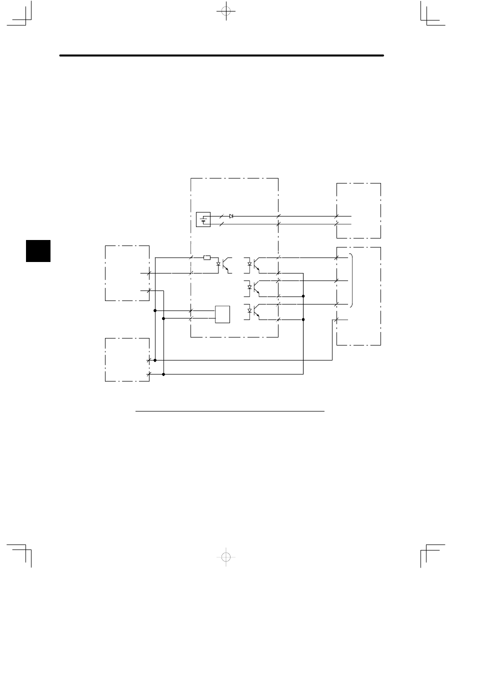
2) Connection Example
A connection example of external power supply/external I/O connector (1CN) is shown in
the following diagram.
PONG
PON
ALM2G
ALM2
ALM1G
ALM1
CHK
CHKG
024V
3CN
1CN
−12
−13
−14
−2
−3
−4
1CN
−11
−1
−15, 16
−5, 6
2CN
+24V
BAT
Battery Module
JRMSP-120XCP96000
Motion Module
Internal connector
Lithium battery
ER6VC3N
Power
circuits
12/24 VDC
Output Module
Sinking
output
Common
Sourcing
inputs
Common
12/24 VDC
Input Module
24-VDC external
power supply
+24 V
024 V
4.7 kΩ
5 mA
5. Battery Voltage Output Connector Terminals (2CN)
1) Connector Pin Arrangements and Signal Names
Backup voltage is supplied from the battery voltage output connector (2CN) through the
Motion Module to the absolute encoder. The connector pin arrangement is shown in the
following illustration.
4