Yaskawa MEMOCON GL120 User Manual
Page 260
System Components: Functions and Specifications
4.4.13 Ethernet Interface Module cont.
— 4-204 —
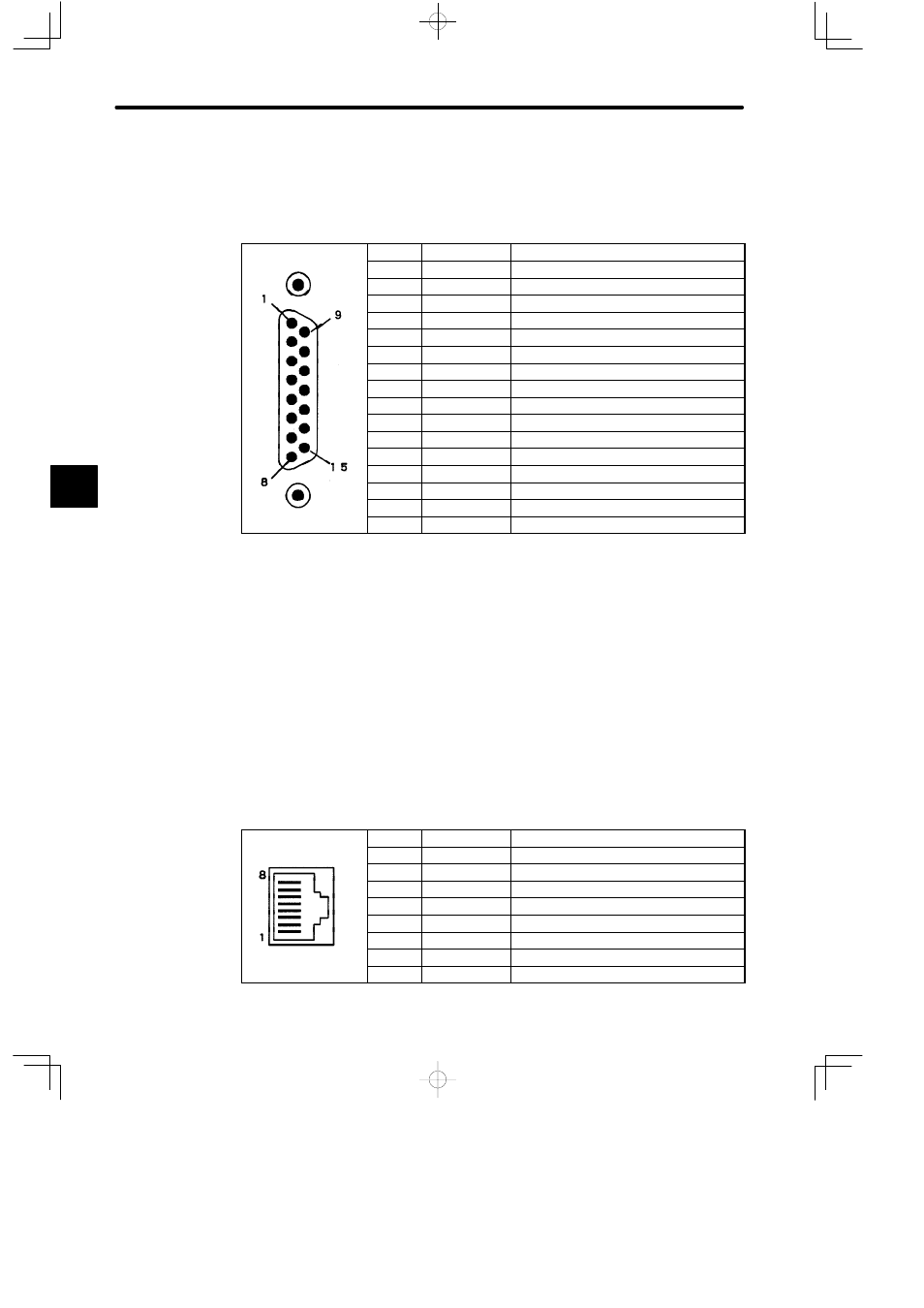
d) A 10Base5 port uses a D-sub connector (15-pin, female). The connector pin arrange-
ment and signal names are shown in the following table.
Table 4.84 Pin Arrangement and Names of Signals for 10Base5 Ports
Pin No.
Symbol
Signal Name
1
CI−S
Control input circuit shield
2
CI−A
Control input circuit A
3
DO−A
Data output circuit A
4
DI−S
Data input circuit shield
5
DI−A
Data input circuit A
6
VC
Power supply common
7
Blank
Control output circuit A
8
CO−S
Control output circuit shield
9
CI−B
Control input circuit B
10
DO−B
Data output circuit B
11
DO−S
Data output circuit shield
12
DI−B
Data input circuit B
13
VP
Power supply positive
14
VS
Power supply shield
15
Blank
Control output circuit B
Shell
PG
Protective ground
5) 10Base-T Port
a) The Ethernet Interface Module can communicate by connecting to a hub (10 Mbps)
on the Ethernet network system via a 10Base-T port. One Ethernet Interface Module
can be connected to and communicate with up to 19 devices.
b) Connection examples for 10Base-T port are shown on page 4-205.
c) For details on 10Base-T port transmission specifications, refer to Table 4.83.
d) A 10Base-T port uses an RJ-45 connector. The connector pin arrangement and sig-
nal names are shown in the following table.
Table 4.85 Pin Arrangement and Names of Signals for 10Base-T Ports
Pin No.
Symbol
Signal Name
1
TXD+
Transmission data+
2
TXD−
Transmission data−
3
RXD+
Reception data+
4
−
Not used.
5
−
Not used.
6
RXD−
Reception data−
7
−
Not used.
8
−
Not used.
4