Yaskawa MEMOCON GL120 User Manual
Page 212
System Components: Functions and Specifications
4.4.7 PC Link Module cont.
— 4-156 —
d) Each pin’s function is shown in the following table.
Table 4.65 Function of DIP Switch
Pin No.
Settings
Function
1
ON
Sets Module to self diagnosis mode.
OFF
Sets Modules to PC Link mode.
2
ON
OFF
Not used. It does not matter whether this pin is ON or OFF.
3
ON
Sets Modules to channel 2 station.
OFF
Sets Modules to channel 1 station.
4
ON
Sets Modules to hold mode. This will hold the contents of data
transmitted from a malfunctioning station to the contents it had
just immediately before the malfunction occurred.
OFF
Sets Modules to clear mode. This will set the contents of data
transmitted from a malfunctioning station to OFF or to all zeros.
5
Set the baud rate of PC Link
S
di
h
bl
Pin 5
Pin 6
Baud rate
6
System according to the table
on the right
ON
ON
4 Mbps
6
on the right.
ON
OFF
2 Mbps
OFF
ON
1 Mbps
OFF
OFF
0.5 Mbps
Note
Set the same baud rate for all the PC Link Modules on the same channel. If baud rate of all the
Modules is not the same, communications will not run.
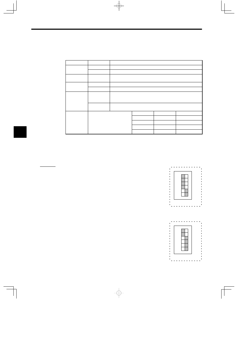
e) Examples of setting the DIP switch are shown below:
Example 1
When the DIP switch is set as shown in the diagram on the right,
the PC Link Module is set as follows:
• PC Link mode
• Channel 1
• Clear mode
• 4 Mbps
Example 2
When the DIP switch is set as shown in the diagram on the right,
the PC Link Module is set as follows:
• PC Link mode
• Channel 2
• Hold mode
• 4 Mbps
4
A
EXAMPLE
"
123456
1
6
SW
ON
123456
1
6
SW
ON