Yaskawa MEMOCON GL120 User Manual
Page 153
4.3 CPU Modules
— 4-97 —
6) Setting Pin 2
a) Pin 2 is used to set communications parameters for MEMOBUS port 2. Set this pin to
meet the requirements of your system.
Table 4.38 Setting Communications Parameters for MEMOBUS Port 2
Pin 2
Function
ON
Sets communications mode of MEMOBUS port 2 to RTU and sets the
communications parameters for the MEMOBUS port 2 to the RTU mode defaults
shown below:
1) Slave address: 1
2) Baud rate:
9,600 bps
3) Parity check:
Yes
4) Parity:
Even
5) Stop bits:
1
6) Data bit length:
8
7) Delay time:
0 ms
OFF
Enables the user to define and set the communications mode and
communications parameters for the MEMOBUS port 2 through a programming
device (Programming Panel, personal computer, etc.).
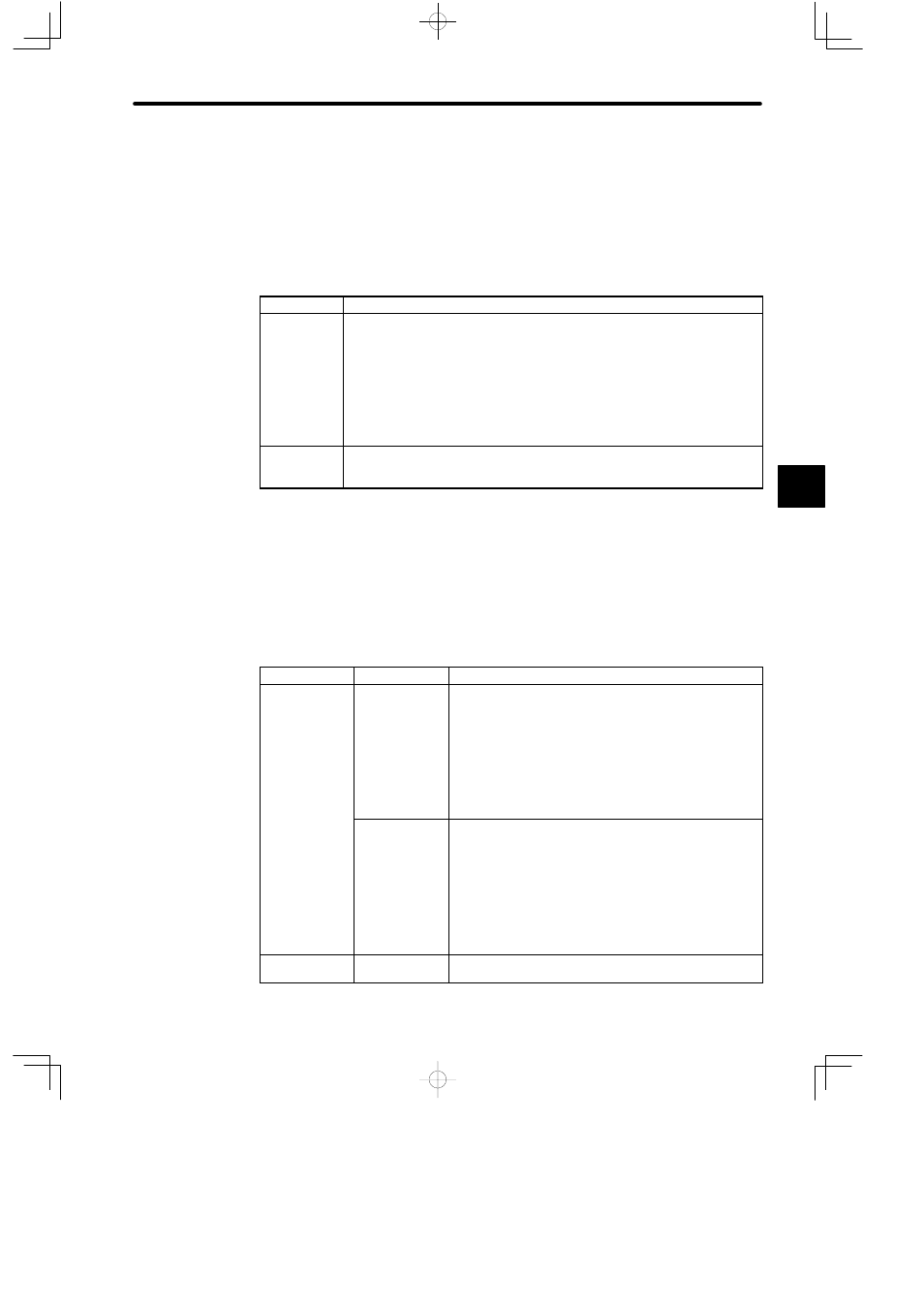
7) Setting Pins 3 and 4
a) Pins 3 and 4 are used to set communications parameters for MEMOBUS port 2. Set
them to meet the requirements of your system.
Table 4.39 Setting Communications Parameters for MEMOBUS Port 2
Pin 3
Pin 4
Function
ON
ON
1) Sets MEMOBUS port 2 as a master port.
2) Master communications (COMM instruction) will be
enabled for MEMOBUS port 2 when the CPU10 Module
is in RUN mode and the communications mode will be
set to Transparent Mode.
3) Slave communications will be enabled when the CPU10
Module is in STOP mode.
OFF
1) Sets MEMOBUS port 2 as a master port.
2) Master communications (COMM instruction) will be
enabled for MEMOBUS port 2 when the CPU10 Module
is in RUN mode and the communications mode will be
set to MEMOBUS Mode.
3) Slave communications will be enabled when the CPU10
Module is in STOP mode.
OFF
ON or OFF
Sets MEMOBUS port 2 as a slave port. Master
communications will be disabled.
4