3 wiring digital i/o modules, Power supply specifications – Yaskawa MEMOCON GL120 User Manual
Page 412
5.3 Panel Wiring
— 5-55 —
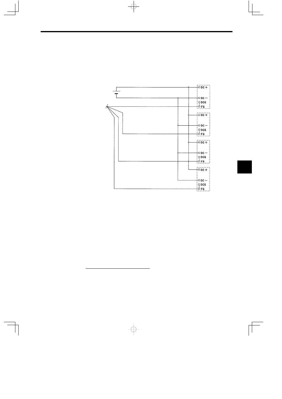
2) DC Power Supply Module
The following diagram shows an example of wiring when four PS11 Power Supply Modules
are used for the local channel. For wiring the protective ground terminals (FG), refer to item
2. Grounding the Power Supply Module under 5.3.5 Grounding.
PS11 Power
Supply
Module for
Rack 1
20.4 to 28.8 VDC
Ripple: 1.0 V
p-p
Ground to a
resistance of
100 Ω max.
PS11 Power
Supply
Module for
Rack 2
PS11 Power
Supply
Module for
Rack 3
PS11 Power
Supply
Module for
Rack 4
5.3.3 Wiring Digital I/O Modules
Connect I/O signal cables to a Digital I/O Module. The connection procedures for I/O signal
cables is described in this section. For further details, refer to the following related manual:
MEMOCON GL120, GL130 120-series I/O Modules User’s Manual
(SIEZ-C825-20.22)
1. Power Supply Specifications
A. AC Power Supply Specifications
1) As shown in Examples 1 and 2 later in this section, it is necessary to supply external
single-phase AC power (100 or 200 VAC) to the I/O Modules listed in the following table to
power input signals and drive loads:
5