3 functions and specifications of i/o modules, Digital input modules – Yaskawa MEMOCON GL120 User Manual
Page 279
4.5 I/O Modules
— 4-223 —
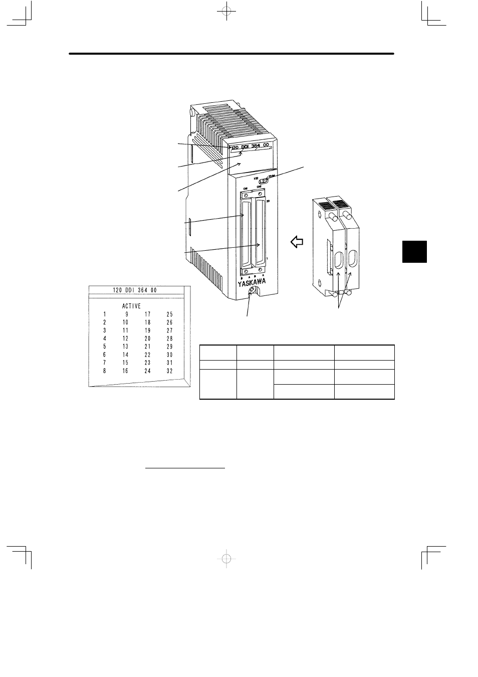
3) The following figure shows the appearance of a12/24-VDC, 64-point Input Module.
Color code
(light blue)
LED area
Module description
(120DDI36400)
I/O signal connector (CN1)
I/O signal connector (CN2)
Connector and covers (2 sets)
Input signal indicator
switch
Module mounting screw
(Use M4 Phillips screwdriver.)
LED
Color
Indication when
ON
Input Signal Indica-
tor Switch
ACTIVE
Green
I/O processing
---
1 to 32
Green
Input signal (1 to 32)
is ON
Left side (1 to 32)
Input signal (33 to
64) is ON
Right side (33 to 64)
Figure 4.67 Appearance of 12/24-VDC 64-point Input Module
4.5.3 Functions and Specifications of I/O Modules
1. Digital Input Modules
1) Function
A Digital Input Module converts the digital signals coming from pushbutton switches, limit
switches, and digital switches into signals of appropriate voltage for PLC internal proces-
4
LED area