Yaskawa MEMOCON GL120 User Manual
Page 187
4.4 Communications Modules
— 4-131 —
Example 2
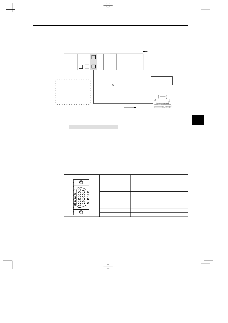
Connecting ASCII Devices
PS10:
Power Supply Module (7 A)
CPU20:
CPU Module (16 KW)
MEM232: MEMOBUS Module (RS-232)
DI:
12/24-VDC 16-point Input Module
DO:
12/24-VDC 16-point Output Module
MC20:
4-axis Motion Module
MB12:
12-slot Mounting Base
W0203-03:MEMOBUS Cable (2.5 m)
W0221-03:MEMOBUS Cable (3.0 m)
M:
MEMOBUS Port
P:
MEMOBUS PLUS Port
Communications by COMM instructions
DI
Set MEMOBUS port of
MEMOBUS Module as follows:
D
Combined master/slave port
D
transparent mode
Data input
Serial printer
(needs to be equipped with
RS-232CI/F)
M
PS10
DI
MEM
232
M
M
P
MB12
Slot No.
MC20
Local channel
Rack 1 (CPU Rack)
CPU20
1
2
3
4
5
6
7
8
9
10
11
12
DI
DO DO
Communications by COMM instructions
M
Bar code reader
(Needs to be equipped
with RS-232CI/F)
Data output
Figure 4.31 Using the MEMOBUS Module (RS-232)
d) The connector for the MEMOBUS port is a D-sub connector (9-pin, female). The con-
nector pin arrangement and signal names are shown in the following table:
Table 4.56 Pin Arrangement and the Signal Names of MEMOBUS Port
Pin No.
Symbol
Signal Name
1
FG
Protective ground
2
TXD
Transmission data
3
RXD
Reception data
4
RTS
Request to send
5
CTS
Clear to send
6
DSR
Data set ready
7
GND
Signal ground
8
−
Not used.
9
DTR
Data terminal ready
4