Yaskawa MEMOCON GL120 User Manual
Page 175
4.4 Communications Modules
— 4-119 —
Example 2
When the DIP switch is set as shown in the diagram on the right,
the Remote I/O Receiver Module is set as follows:
• Module in remote mode.
• MEMOBUS port is used as combined master/slave port.
• When MEMOBUS port is used as master port, communications
mode is in transparent mode.
• When MEMOBUS port is used as slave port, communications
mode and parameters are set to the defaults.
• Baud rate of Remote I/O System is 4 Mbps.
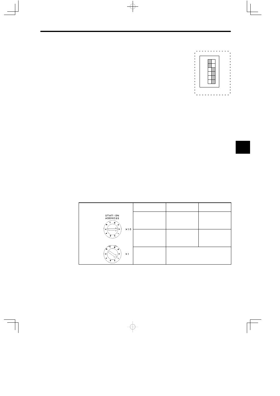
6) Rotary Switches
a) The rotary switches are used to set the station address of the Remote I/O Receiver
Module.
b) There are two rotary switches. The top rotary switch is rotary switch 1 and the bottom
switch is rotary switch 2. Each switch has positions from 0 to 9.
c) The settings of the rotary switches are effective (read) when the reset switch is
pressed, or when power is turned ON to the Power Supply Module of the Rack where
the Remote I/O Receiver Module is mounted.
d) Station addresses are set between 1 and 15. The following table shows the settings.
Table 4.50 Setting the Station Address
Example
Settings of Node Address 1
Node Address
Rotary Switch 1
Rotary Switch 2
Rotary switch 1
1 to 9
0
1 to 9
Rotary switch 1
10 to 15
1
0 to 5
Rotary switch 2
0 or 16 to 99
Not permitted.
Note
(1) Set the station address to between 1 and 15. If the address is set to 0 or, to 16 or above,
normal communications will not be possible.
(2) Do not use the same address for more than one station within the same channel. If this
occurs, remote stations with the same address will not be able to communicate nor-
mally.
4
123456
1
6
SW
ON