Yaskawa MEMOCON GL120 User Manual
Page 300
System Components: Functions and Specifications
4.6.3 Pulse Catch Module cont.
— 4-244 —
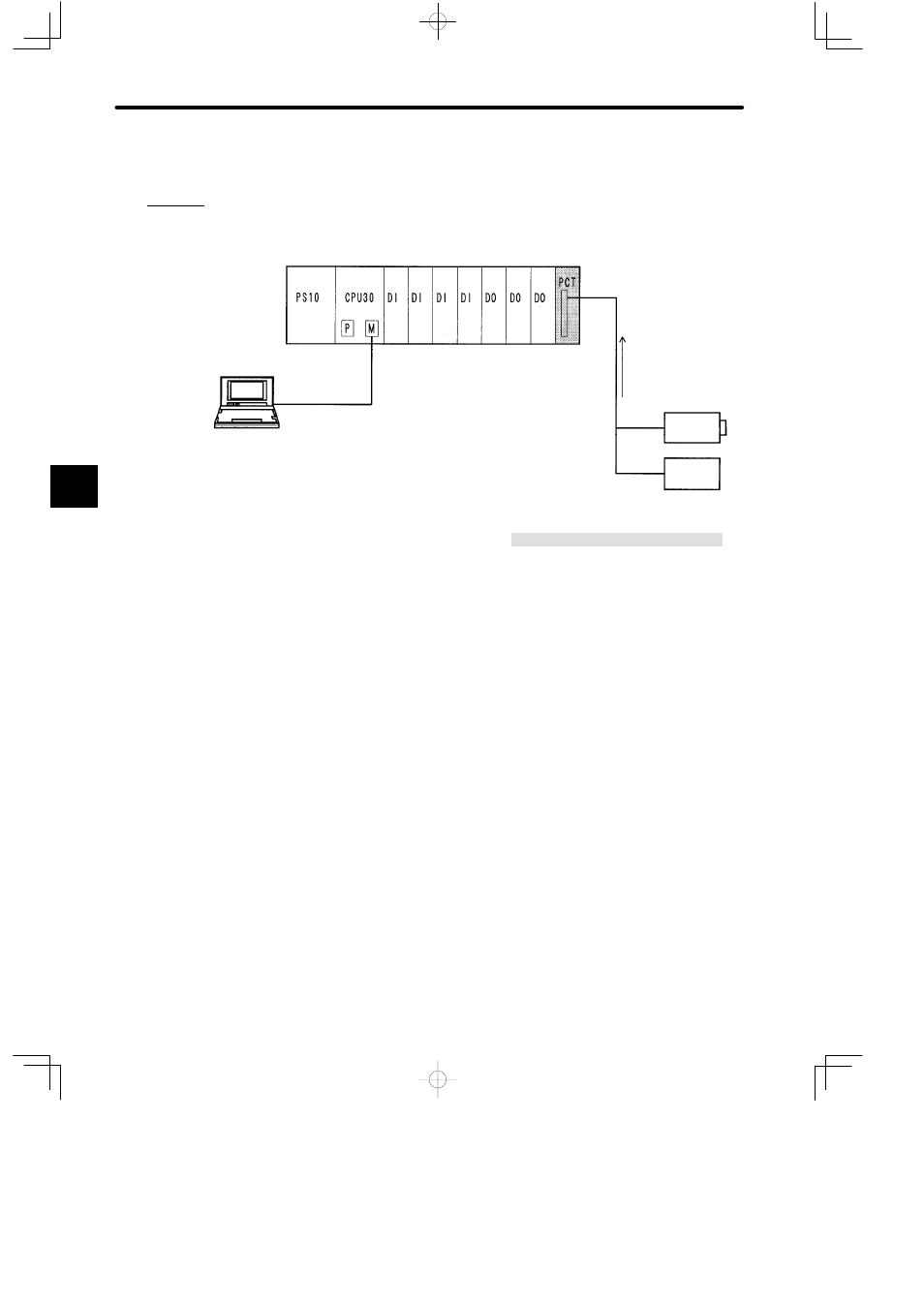
3) Example of System Configuration
The following diagram shows an example of a system configuration where a Pulse Catch and
Counter Module is used for counting.
PS10:
Power Supply Module (7 A)
CPU30:
CPU Module (32 KW)
DI:
12/24-VDC 16-point Input Module
DO:
12/24-VDC 16-point Output Module
PCT:
Pulse Catch and Counter Module
MB12:
12-slot Mounting Base
W0203-03:MEMOBUS Cable (2.5 m)
Local channel, rack 1 (CPU Rack)
Open-collector
output, 24 VDC
Rotary
encoder
P120C
Programming Panel
DC power
supply
24 VDC
MB12
W0203-03
Figure 4.74 Using Pulse Catch Modules
4) Related Manuals
Before operating a Pulse Catch Module, read the following manual carefully and be sure
that you fully understand the information on specifications, application methods, safety
precautions, etc.
MEMOCON GL120, GL130 Pulse Catch and Counter Module User’s Manual
(SIEZ-C825-20.24)
4
A
EXAMPLE
"