7 pc link module, Appearance – Yaskawa MEMOCON GL120 User Manual
Page 203

4.4 Communications Modules
— 4-147 —
4.4.7 PC Link Module
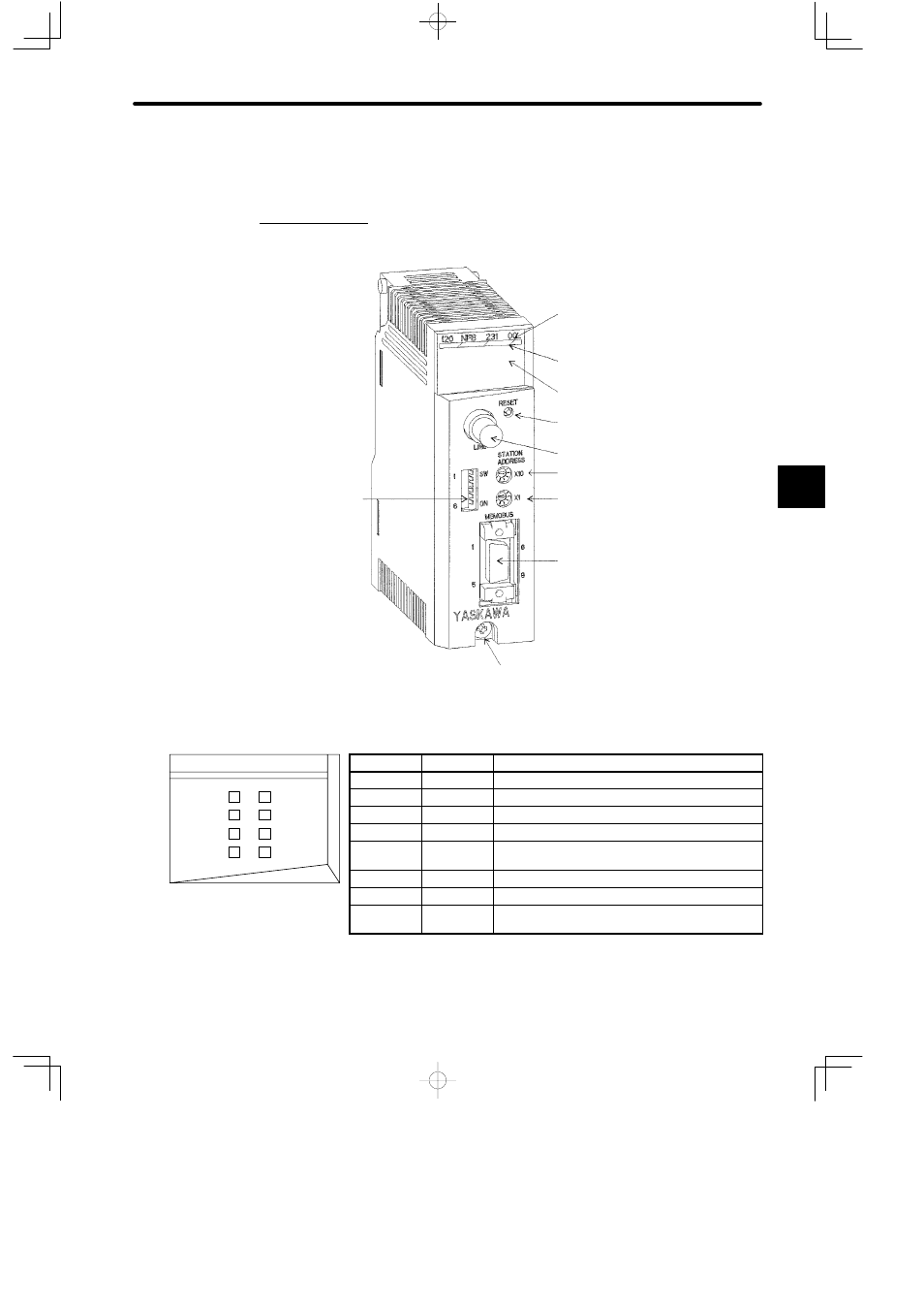
1. Appearance
DIP switch
Rotary switch 2
MEMOBUS port
Module Description
(120NFB23100)
Color code (yellow)
LED area
PC Link port
Reset switch
Rotary switch 1
Module mounting screw
(Use M4 Phillips screwdriver.)
LED
Color
Indication when ON
READY
Green
Module is operating normally.
ACTIVE
Green
Module is engaged in service with the CPU Module
L-TX
Green
Module is transmitting data from PC Link port.
L-RX
Green
Module is receiving data from PC Link port.
L-ERR
Red
An error has occurred in the transmission of PC
Link port. Lit for 10 ms.
PP TX
Green
Module is transmitting data from MEMOBUS port.
PP RX
Green
Module is receiving data from MEMOBUS port.
PP ERR
Red
An error has occurred in the transmission of
MEMOBUS port.
Figure 4.38 Appearance of PC Link Module
4
L-TX
READY
120 NBF 231 00
L-RX
L-ERR
ACTIVE
PP TX
PP RX
PP ERR
LED area
