Yaskawa MEMOCON GL120 User Manual
Page 22
!
!
1.2
Precautions
— 1-17 —
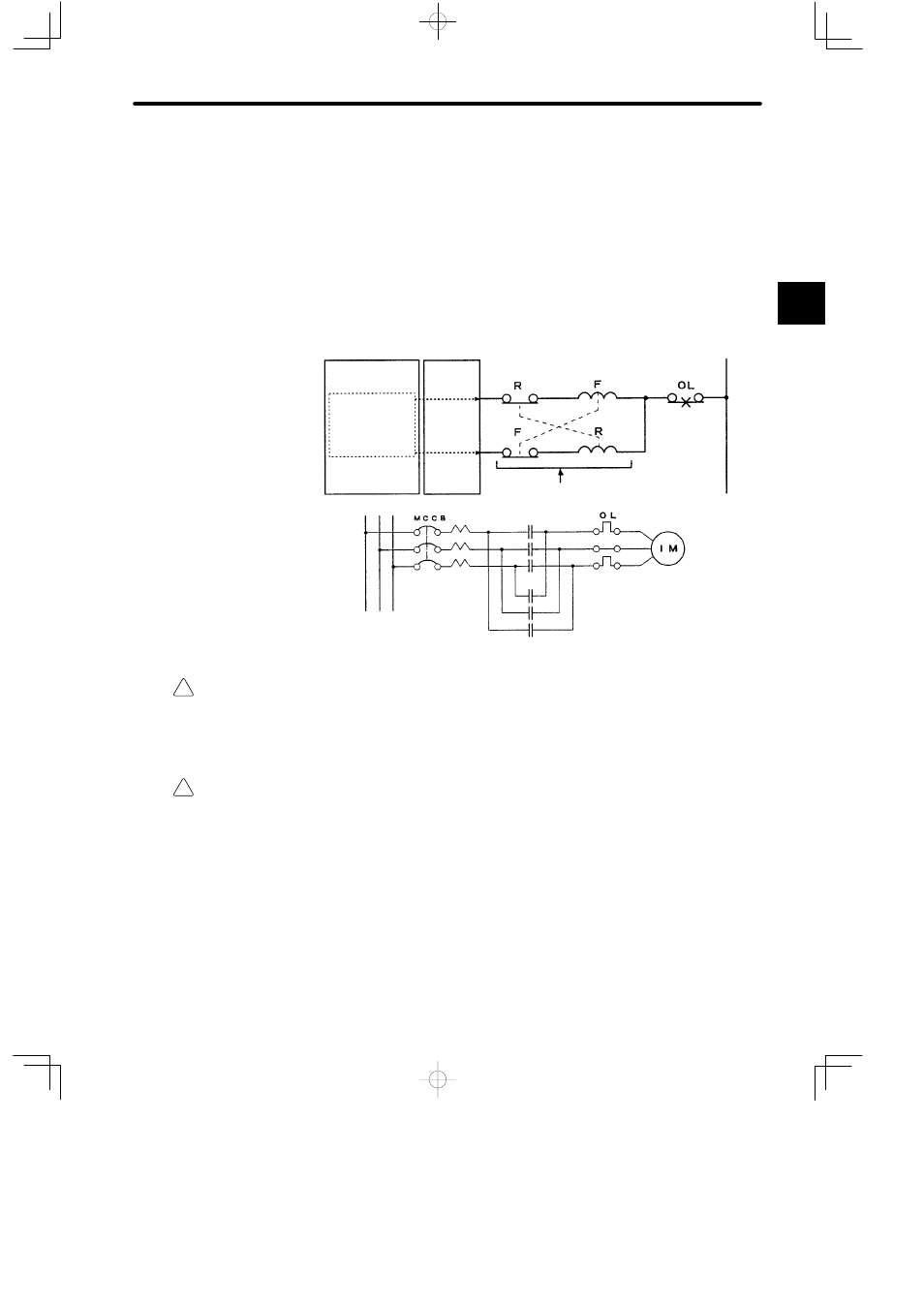
External Interlocks for the GL120 and GL130
Externally connect an interlock to the GL120 and GL130 if there is any chance that
GL120 and GL130 failure could result in bodily harm or equipment damage.
Always use an external interlock system as shown in the following example when recip-
rocal operations (e.g., forward and reverse directions) are being performed with a motor.
An interlock is generally programmed in the GL120/GL130 ladder program to ensure that
forward and reverse signals are not simultaneously output. An external interlock circuit
must also be provided using the auxiliary contacts of electromagnetic contactors.
CPU Module
Output Module
Ladder logic program
Output program with an
interlock which prohibit
simultaneous forward
and reverse runs
Contact of over-
current protection
device.
Electric interlock using the auxiliary contacts
of electromagnetic contactors
R (Reverse run)
F (Forward run)
Induction motor
Caution
Always make sure that power supply to the external power supply terminals (AC1, AC2) is
OFF when operating the input voltage selector switch of Power Supply Module.
Operating the input voltage selector switch of Power Supply Module while power is being
supplied to the external power supply terminals may damage the Module.
Caution
Set the Rack numbers according to the following rules.
If the Rack No. is not set according to the following rules, the PLC system will not run
normally. In other words, it may result in failure of the CPU Module to run, communication
errors, I/O process errors, etc.
• Set each Rack No. between 1 and 4 (rotary switch No: between 0 and 3).
• Always set the Rack No. where CPU Module or Remote I/O Receiver Module is
installed to 1 (rotary switch: 0).
• Do not use the same Rack No. more than once at the same station.
1