Yaskawa MEMOCON GL120 User Manual
Page 210
System Components: Functions and Specifications
4.4.7 PC Link Module cont.
— 4-154 —
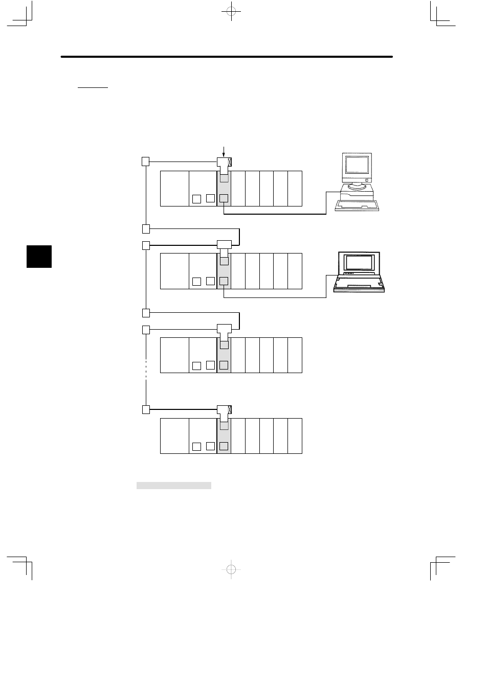
Example 2
Connecting ACGC4250 FA Monitor and P120 Programming Panel.
The ACGC4250 FA Monitor and P120C Programming Panel can run communications with all
the CPU Modules through the PC Link System.
PS10:
Power Supply Module (7 A)
CPU20:
CPU Module (16 KW)
CPU30:
CPU Module (32 KW)
LNC:
PC Link Module
DI:
12/24-VDC 16-point Input Module
DO:
12/24-VDC 16-point Output Module
MB10:
10-slot Mounting Base
W0203-03:MEMOBUS Cable
W0204-05:MEMOBUS Cable
M
DI
LNC
PS10
DI
DI
P
MB10
CPU30
PC Link channel 1, station 3
T
C
DO DO
M
DI
LNC
PS10
DI
DI
P
MB10
CPU30
A
A
Conversion
Adapter
Branch line coaxial cable*1
T-adapter
R (Terminator) PC Link channel 1, station 1
Main line
coaxial cable*2
A
*1
*1
A
A
*1
*1
A
*1
*2
*2
T
C
DO DO
M
DI
LNC
PS10
DI
DI
P
MB10
CPU20
PC Link channel 1, station 2
T
C
DO DO
M
DI
LNC
PS10
DI
DI
P
MB10
CPU20
PC Link channel 1, station 32
T
C
DO DO
M
M
M
M
ACGC4250 FA Monitor
W0204-05
P120C Programming
Panel
W0203-03
Figure 4.41 Connecting ACGC4250 FA Monitor and P120 Programming Panel
4
A
EXAMPLE
"