Yaskawa MEMOCON GL120 User Manual
Page 154
Ver.
B01
IMPORTANT
Ver.
B01
System Components: Functions and Specifications
4.3.6 Using CPU Modules 3 (For CPU10) cont.
— 4-98 —
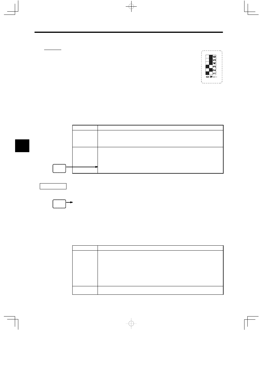
b) A setting example for pins 3 and 4 is shown below.
(1) When the DIP switch pins 2 and 3 are set as shown in the dia-
gram on the right, the communications parameters of ME-
MOBUS port 2 are set to MEMOBUS mode and a master
port.
8) Setting Pin 5
Pin 5 is used to set the start mode of the CPU10 Module. Refer to the following table to set
the start mode for your system.
Table 4.40 Setting the Start Mode
Pin 5
Function
ON
1) Sets the start mode of the CPU10 Module to automatic RUN operation.
2) In this mode, the CPU10 Module will start in RUN mode when power is
turned ON to the CPU Rack.
OFF
1) Sets the start mode of the CPU10 Module to normal operation.
2) In this mode, the CPU10 Module will start in the mode it was in just before
the power supply was turned OFF (i.e., either RUN or STOP mode).
3) If DIP switch pin 6 is set for ROM operation, the CPU10 will start in STOP
mode. (Ver. B01 onwards)
The setting of pin 5 is effective (read) only when power is turned ON to the Power Supply
Module of the CPU Rack.
9) Setting Pin 6
a) Pin 6 is used to set whether or not ROM operation will be used when power is turned
ON to the CPU10 Module. Refer to the following table to set ROM operation if required
for your system.
Table 4.41 ROM Operation Setting
Pin 6
Function
ON
1) Sets the CPU10 Module to ROM operation. The ladder program, holding
register data, and other data stored in the flash ROM will be transferred to
RAM when the power supply is turned ON to the CPU Rack.
2) If the ladder logic program, holding register data, and other data is not stored
in the flash ROM when the power supply is turned ON to the CPU Rack, a
ROM operation error will occur and the CPU10 Module will start in STOP
mode.
OFF
Sets the CPU10 Module to RAM operation. The RAM data will be used for
operation when the power supply is turned ON to the CPU Rack.
4
A
EXAMPLE
"