Yaskawa MEMOCON GL120 User Manual
Page 292
System Components: Functions and Specifications
4.6.2 High-speed Counter Module cont.
— 4-236 —
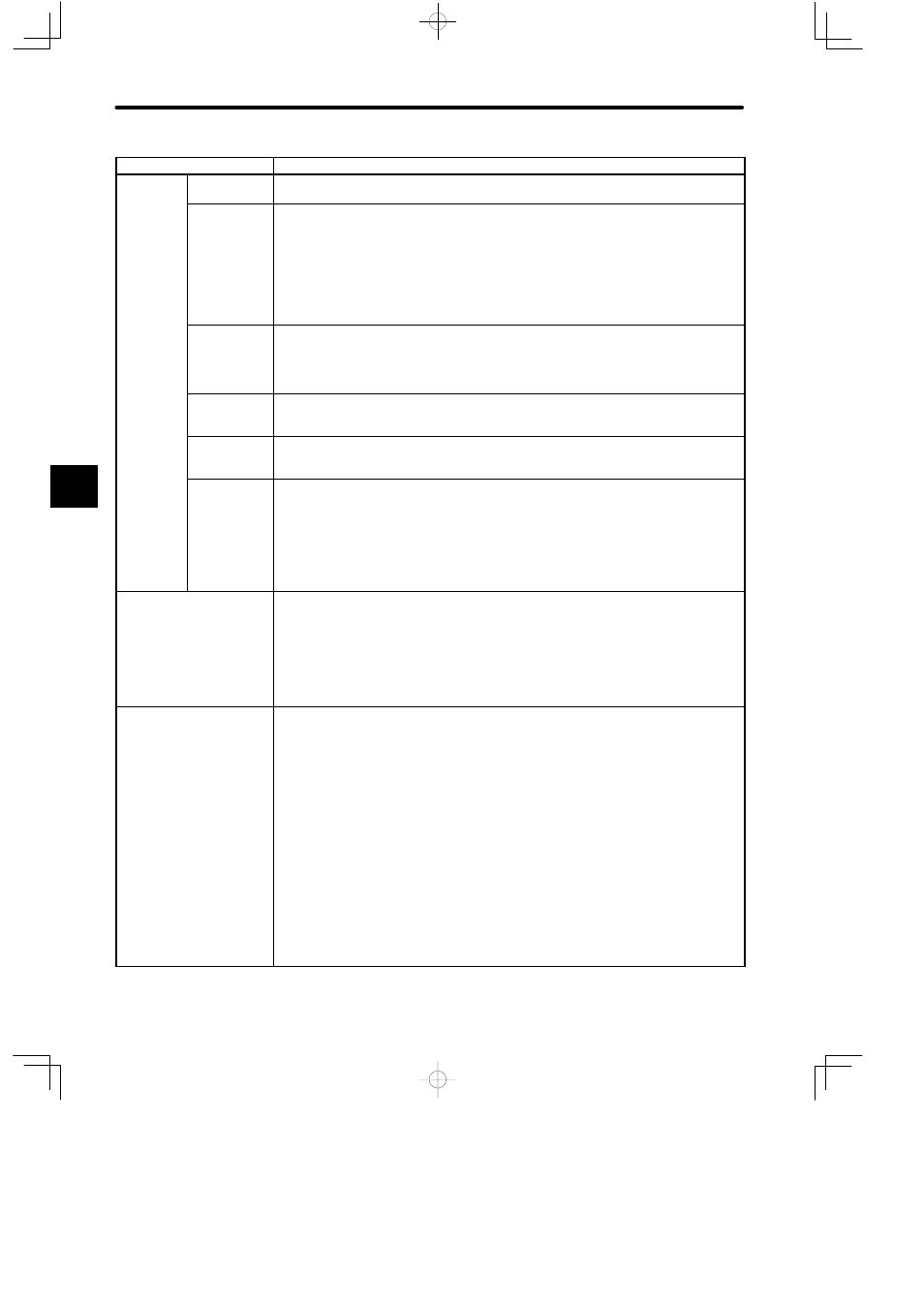
Items
Specifications
Notch Sig-
nal Output
Number of
Output Signals
Four notch signal points can be output to external devices such as relays.
a O p
Specifica-
tions for
Notch Output
Mode
1) Set the initial setting of the output mode of each notch signal either to state mode or to
latch mode from the ladder program.
2) The notch signals set in state mode will be ON if the current position of counter is within
the range of set notch point.
3) The notch signals set in latch mode will turn ON when the current position of counter
reaches the set notch point. To turn these signals OFF, turn the latch reset signal ON
from the ladder program.
Notch Point
Set Value
1) Set the initial setting of the ON/OFF timing of the notch signal at each notch point from
the ladder program.
2) Notch point set value in state mode: 2 points
Notch point set value in latch mode: 1 point
Forced
Outputs
Function
Each notch signal can be forced ON or OFF from the ladder program.
External
Outputs
Circuit
Specifications of the output circuit of each notch signal:
Open collector output, 12/24 VDC, 100 mA
Internal
Control Signal
The following signals can be output to the High-speed Counter Module from the ladder pro-
gram.
1) Notch output enable:
The High-speed Counter Module can output notch signals while this signal is ON.
2) Latch reset:
The notch signals that turned ON in latch mode can be turned OFF by turning this
signal ON.
Status when ACTIVE is OFF Set the initial setting of the status mode when ACTIVE is OFF from the ladder program.
1) Count continue mode:
In this mode, the High-speed Counter Module will count the pulses even when ACTIVE
is OFF.
2) Count stop mode:
In this mode, the High-speed Counter Module will not count the pulses when ACTIVE is
OFF.
Monitor Functions
The following signal can be monitored from the ladder program.
1) READY: High-speed Counter Module is normal and ON.
2) ACK: The High-speed Counter Module has been successfully set and it is ON.
3) ERROR: ON when a setting error has occurred.
4) NOTCH OUTPUT 0: ON when notch output 0 is ON.
5) NOTCH OUTPUT 1: ON when notch output 1 is ON.
6) NOTCH OUTPUT 2: ON when notch output 2 is ON.
7) NOTCH OUTPUT 3: ON when notch output 3 is ON.
8) CARRY: ON for one scan when the pulse count is incremented over the count width
and has changed to 0 .
9) BORROW:
ON for one scan when the pulse count has been decremented past 0 and
has changed to the count width value.
4