Yaskawa MEMOCON GL120 User Manual
Page 32
Overview
— 2-8 —
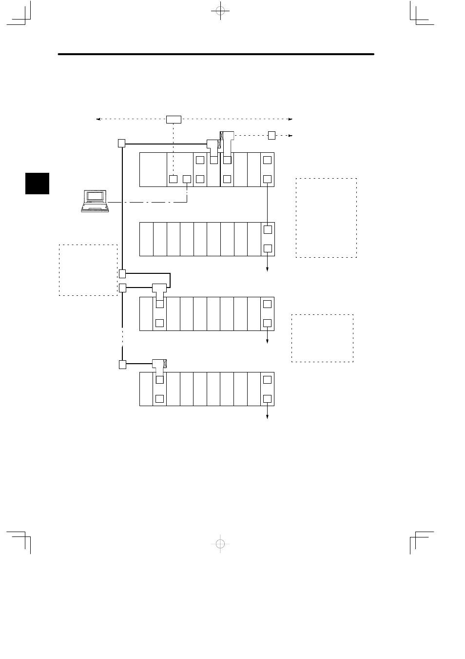
6) Figure 2.2 shows GL120 and GL130 system configurations.
EXP
I/O
I/O
I/O
I/O
I/O
I/O
I/O
I/O
PS
05
EXP
I/O
I/O
I/O
I/O
I/O
I/O
I/O
PS
05
RRC
M
EXP
I/O
I/O
I/O
I/O
I/O
I/O
I/O
PS
05
RRC
M
C
R
EXP
I/O
I/O
CPU30
PS10
LNC
M
C
RDC
MEM
422
M
M
M
P
MB10
MB10
MB10
MB10
A
A
A
A
HUB
A
GL130
Previous node
MEMOBUS PLUS Cable
Next node
PC Link Cable
Remote I/O Cable
Can be extended up to Rack 4.
MEMOBUS
PLUS Networks
D
One network per PLC
D
Twisted-pair cable
D
1 Mbps (fixed)
D
Without Repeater
450 m max.
32 nodes max.
D
With Repeater
1,800 m max.
64 nodes max.
Remote I/O Systems
D
Two systems per PLC
D
Coaxial cable
D
4 Mbps max.
D
1 km max.*
D
15 stations max.
Next station
W0203-02
Local
channel
Rack 1
(CPU Rack)
W0100-02
Local
channel
Rack 2
Rack 1
Rack 1
PC Link system
T
T
T
T
R
C
C
Station 1
Programing Panel P120C
Station 1 of remote channel 1
D
Two systems per PLC
D
Coaxial cable
D
4 Mbps max.
D
1 km max.
D
32 stations max.
Can be extended up to Rack 4.
Can be extended up to Rack 4.
Station 15 of remote channel 1
Figure 2.1 Outline of GL120/GL130 System Configuration
* The transmission distance varies according to the baud rate and specifications of the coax-
ial cable. For example, if the baud rate is 4 Mbps and the 12C-5AF Coaxial Cable is used, it
is possible to transmit up to 1 km max.
2