Reset and hardware strapping timing – Digi NS9750 User Manual
Page 859
w w w . d i g i e m b e d d e d . c o m
8 3 5
T i m i n g
Reset and hardware strapping timing
Note:
All AC characteristics are measured with 10pF, unless otherwise noted.
Table 479 describes the values shown in the reset and hardware strapping timing
diagram (Figure 144).
Note:
1
The hardware strapping pins are latch 5 clock cycles after
reset_n
is deasserted (goes high).
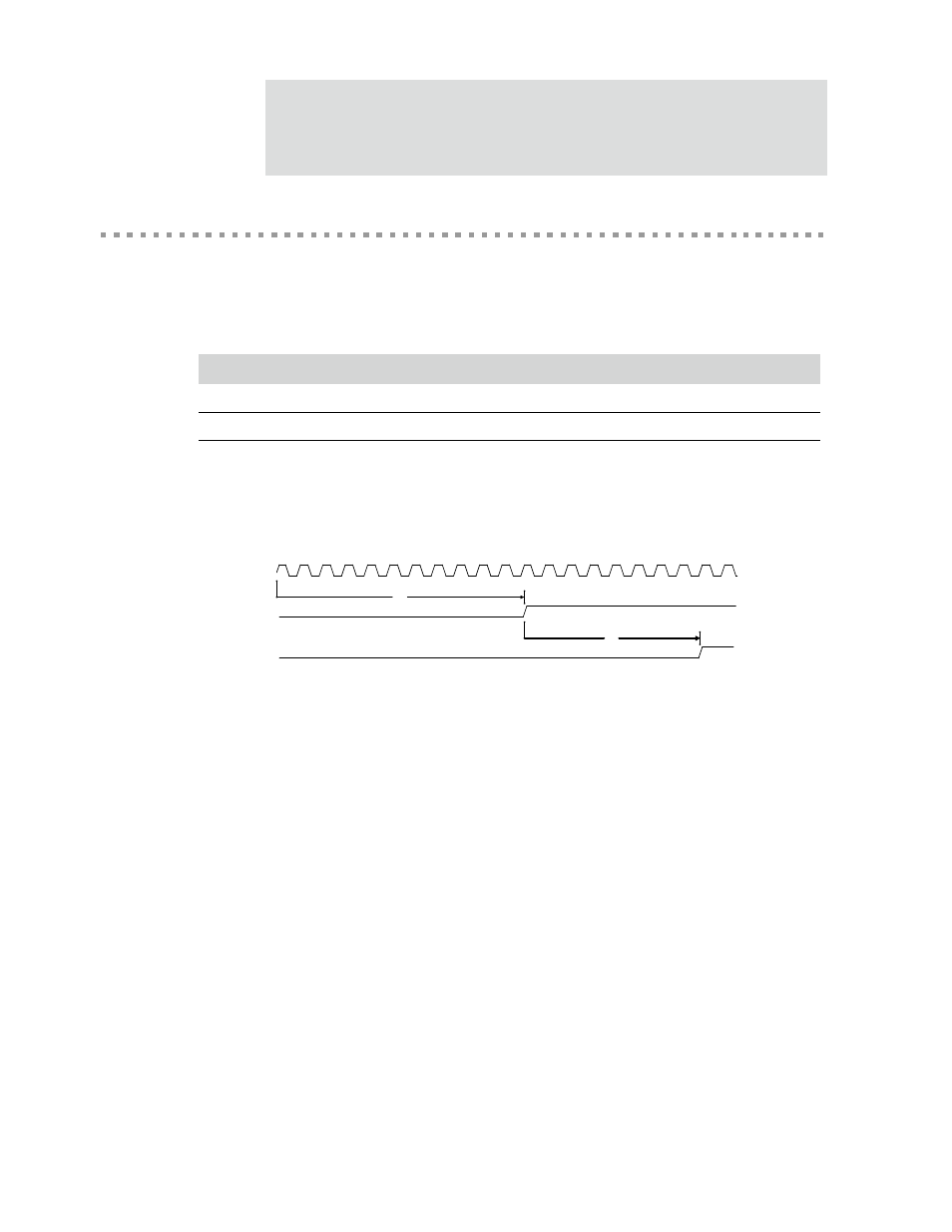
Figure 144: Reset and hardware strapping timing
R1:
reset_n
must be held low for a minimum of 10
x1_sys_osc
clock cycles after
powerup.
R2:
reset_done
is asserted 4ms after
reset_n
is driven high.
The hardware strapping pins are latched when
reset_done
is asserted.
Parm
Description
Min
Max
Unit
Notes
R1
reset_n minimum time
10
x1_sys_osc clock cycles
1
R2
reset_n to reset_done
4
ms
Table 479: Reset and hardware strapping timing parameters
R1
R2
x1_sys_osc
reset_n
reset_done