C external addresses, C command interface – Digi NS9750 User Manual
Page 569
w w w . d i g i e m b e d d e d . c o m
5 4 5
I 2 C M a s t e r / S l a v e I n t e r f a c e
I
2
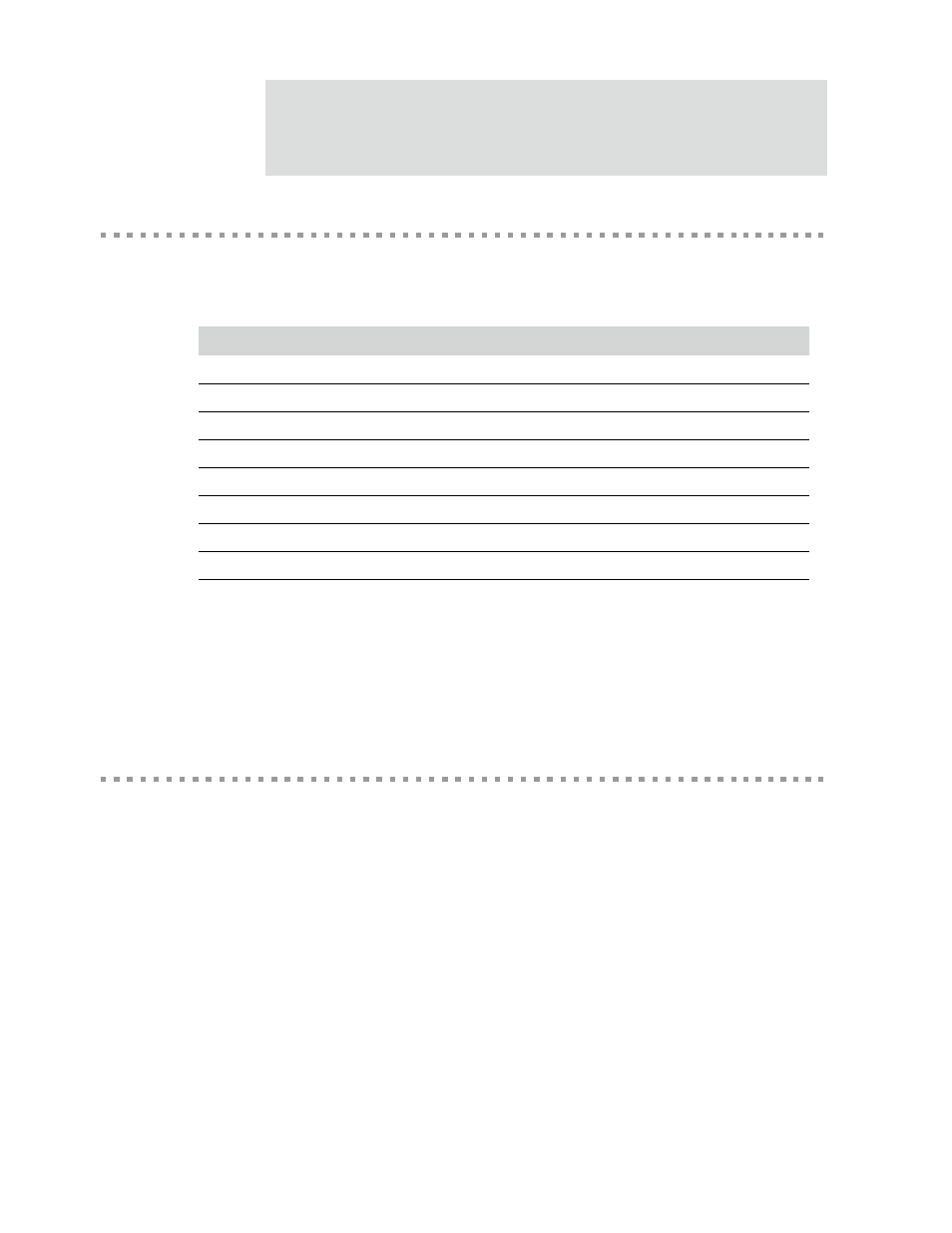
C external addresses
I
2
C external [bus] addresses are allocated as two groups of eight addresses (
0000XXX
and
1111XXX
), as shown in Table 334.
The general call address is for addressing all devices connected to the I
2
C bus. A
device can ignore this address by not issuing an acknowledgement. The meaning of
the general call address is always specified in the second byte.
I
2
C command interface
The I
2
C module converts parallel (8-bit) data to serial data and serial data to parallel
data between the NS9750 and the I
2
C bus, using a set of interface registers.
The primary interface register for transmitting data is the
CMD_TX_DATA_REG
(write-only).
The primary interface register for receiving data is the
STATUS_RX_DATA_REG
(read-only).
Slave address
R/W bit
Description
0000 000
0
General call address
0000 000
1
START byte (not supported in NS9750)
0000 001
X
CBUS address (not supported in NS9750)
0000 010
X
Reserved for different bus format
0000 011
X
Reserved
0000 1xx
X
hs-mode master code (not supported in NS9750)
1111 1xx
X
Reserved
1111 0xx
X
10-bit slave address
Table 334: Reserved slave addresses