Control register, Table 138: control register – Digi NS9750 User Manual
Page 229
w w w . d i g i e m b e d d e d . c o m
2 0 5
M e m o r y C o n t r o l l e r
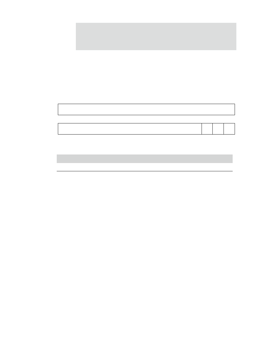
Control register
Address: A070 0000
The Control register controls the memory controller operation. The control bits can
be changed during normal operation.
Register bit assignment
Bits
Access
Mnemonic
Description
D31:03
N/A
Reserved
N/A (do not modify)
D02
R/W
LPM
Low-power mode
0
Normal mode (reset value on
reset_n
and
HRESETn
)
1
Low-power mode
Indicates normal or low-power mode. Entering low-power mode
reduces memory controller power consumption. Dynamic memory
is refreshed as necessary. The memory controller returns to normal
functional mode by clearing the low-power mode bit, by AHB, or by
power-on reset.
If you modify this bit, be sure the memory controller is in idle state.
If you modify the L bit, be aware of these conditions:
The external memory cannot be accessed in low-power or
disabled state. If a memory access is performed in either of
these states, an error response is generated.
The memory controller AHB programming port can be
accessed normally.
The memory controller registers can be programmed in low-
power and/or disabled state.
Table 138: Control register
MCEN
13
12
11
10
9
8
7
6
5
4
3
2
1
0
15
14
31
29
28
27
26
25
24
23
22
21
20
19
18
17
16
30
Reserved
Reserved
LPM ADDM