Bbus bridge interrupt status register – Digi NS9750 User Manual
Page 522
B B u s B r i d g e C o n t r o l a n d S t a t u s r e g i s t e r s
4 9 8
N S 9 7 5 0 H a r d w a r e R e f e r e n c e
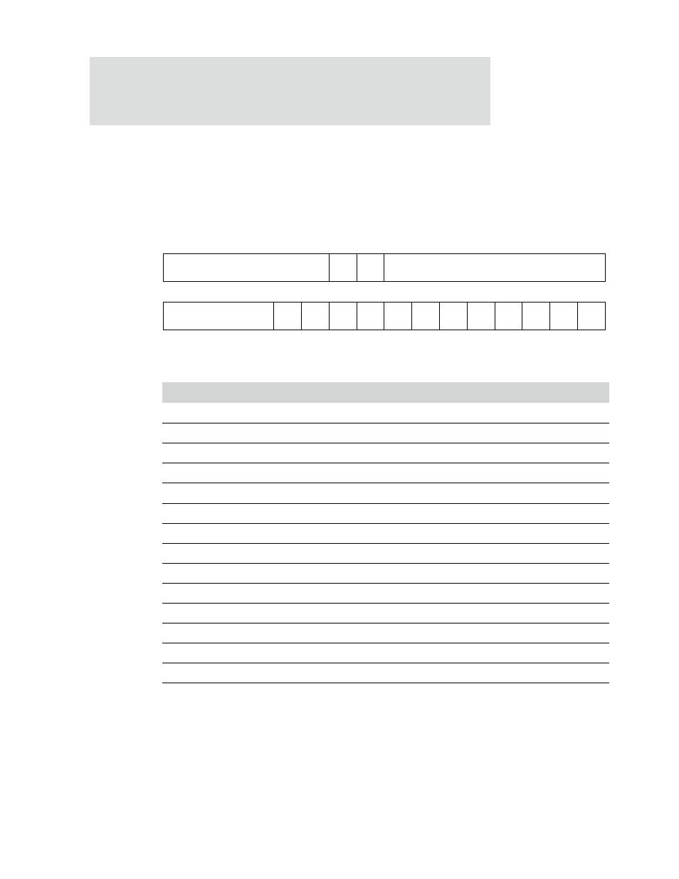
BBus Bridge Interrupt Status register
Address: A040 1000
This register contains the interrupt status of the BBus peripherals. All interrupts must
be serviced in the originating module.
Register bit assignment
Bits
Access
Mnemonic
Reset
Description
D31:26
R
Not used
00
Always set this field to 0.
D25
R
ADMA2
0
AHB DMA channel #2 has asserted its interrupt.
D24
R
ADMA1
0
AHB DMA channel #1 has asserted its interrupt.
D23:13
R
Not used
0x000
Always set this field to 0.
D12
R
Not used
0
Always write to 0.
D11
R
1284
0
IEEE-1284 module has asserted its interrupt.
D10
R
I2C
0
I2C module has asserted its interrupt.
D09
R
SDTX
0
SER transmit module D has asserted its interrupt.
D08
R
SDRX
0
SER receive module D has asserted its interrupt.
D07
R
SCTX
0
SER transmit module C has asserted its interrupt.
D06
R
SCRX
0
SER receive module C has asserted its interrupt.
D05
R
SATX
0
SER transmit module A has asserted its interrupt.
D04
R
SARX
0
SER receive module A has asserted its interrupt.
D03
R
SBTX
0
SER transmit module B has asserted its interrupt.
D02
R
SBRX
0
SER receive module B has asserted its interrupt.
Table 300: BBus Bridge Interrupt Status register
Not used
I2C
1284
S4TX
S4RX
S3TX
S3RX
S2TX
S2RX
S1TX
S1RX
USB
BBDMA
13
12
11
10
9
8
7
6
5
4
3
2
1
0
15
14
31
29
28
27
26
25
24
23
22
21
20
19
18
17
16
30
ADMA2
ADMA1
Not used
Not used