Brc0, brc1, brc2, and brc3 registers – Digi NS9750 User Manual
Page 307
w w w . d i g i e m b e d d e d . c o m
2 8 3
S y s t e m C o n t r o l M o d u l e
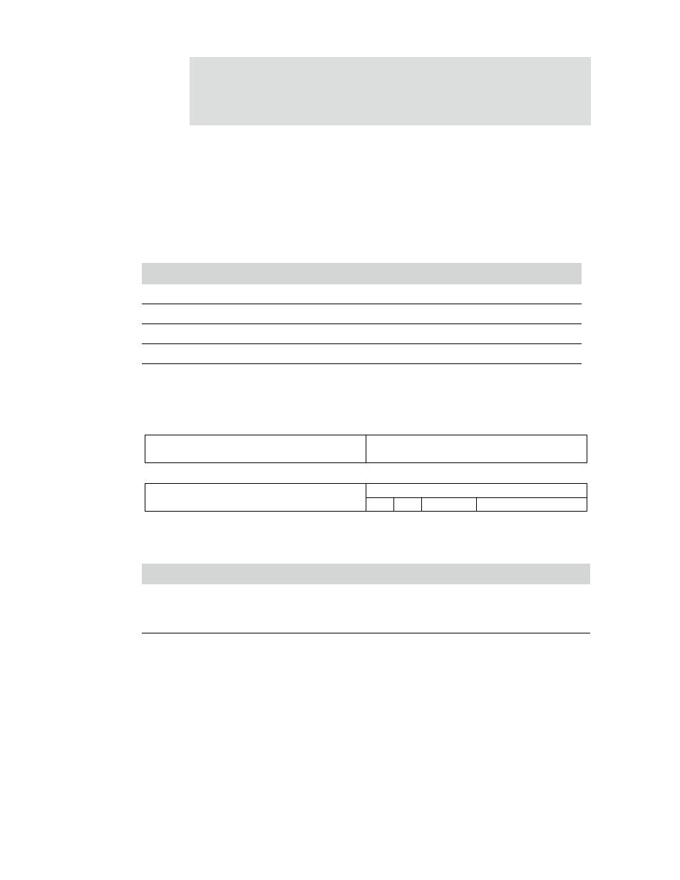
BRC0, BRC1, BRC2, and BRC3 registers
Address: A090 0004 / 0008 / 000C / 0010
The BRC[0:3] registers control the AHB arbiter bandwidth allocation scheme.
Table 172 shows how the channels are assigned in the four registers. Table 173 shows
the bit definition, or format, for each channel, using data bits [07:00] as the
example.
Register bit assignment
Register name
[31:24]
[23:16]
[15:08]
[07:00]
BRC0
Channel 0
Channel 1
Channel 2
Channel 3
BRC1
Channel 4
Channel 5
Channel 6
Channel 7
BRC2
Channel 8
Channel 9
Channel 10
Channel 11
BRC3
Channel 12
Channel 13
Channel 14
Channel 15
Table 172: BRC channel assignment
Bits
Access
Mnemonic
Reset
Description
D07
R/W
CEB
0x0
Channel enable bit
0
Disable
1
Enable
D06
N/A
Reserved
N/A
N/A
Table 173: BRC0, BRC1, BRC2, BRC3 register
HMSTR
13
12
11
10
9
8
7
6
5
4
3
2
1
0
15
14
31
29
28
27
26
25
24
23
22
21
20
19
18
17
16
30
Channel 0, 4, 8, or 12
Channel 1, 5, 9, or 13
Channel 2, 6, 10, or 14
Channel 3, 7, 11, or 15
CEB
Rsvd
BRF