Lcd module signals – Digi NS9750 User Manual
Page 66
P i n o u t a n d s i g n a l d e s c r i p t i o n s
4 2
N S 9 7 5 0 H a r d w a r e R e f e r e n c e
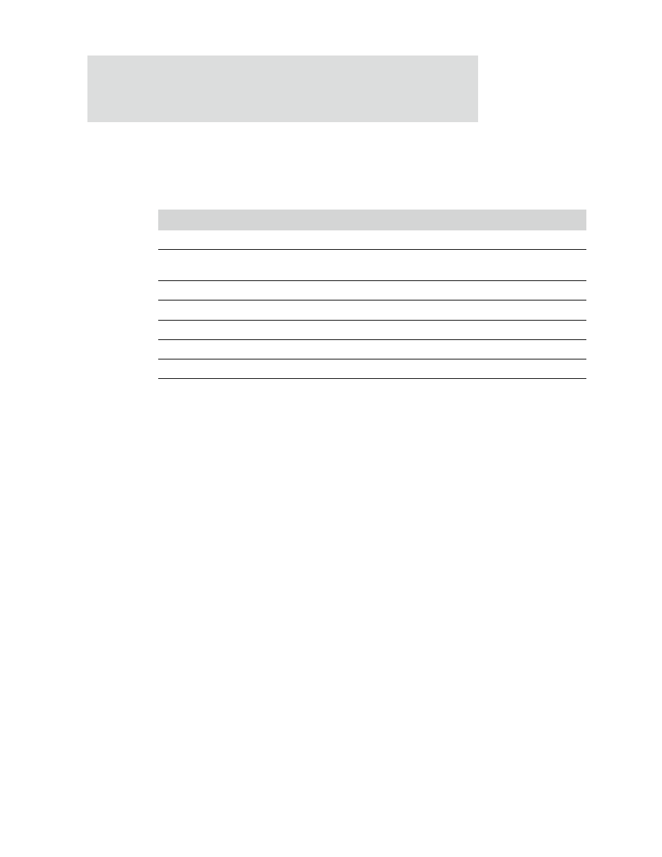
LCD module signals
The LCD module signals are multiplexed with GPIO pins. They include seven control
signals and up to 24 data signals. Table 11 describes the control signals.
The
CLD[23:0]
signal has eight modes of operation:
See the discussion of LCD panel signal multiplexing details for information about the
CLD
signals used with STN and TFT displays.
Signal name
Type
Description
CLPOWER
Output
LCD panel power enable
CLLP
Output
Line synchronization pulse (STN) / horizontal synchronization pulse
(TFT)
CLCP
Output
LCD panel clock
CLFP
Output
Frame pulse (STN) / vertical synchronization pulse (TFT)
CLAC
Output
STN AC bias drive or TFT data enable output
CLD[23:0]
Output
LCD panel data
CLLE
Output
Line end signal
Table 11: LCD module signal descriptions
TFT 24-bit interface
4-bit mono STN single panel
TFT 18-bit interface
4-bit mono STN dual panel
Color STN single panel
8-bit mono STN single panel
Color STN dual panel
8-bit mono STN dual panel