Static write cycle with configurable wait states, Wtwr = from 0 to 15, Signals will go low. during a 16-bit transfer, two – Digi NS9750 User Manual
Page 834: Signal will go low
M e m o r y t i m i n g
8 1 0
N S 9 7 5 0 H a r d w a r e R e f e r e n c e
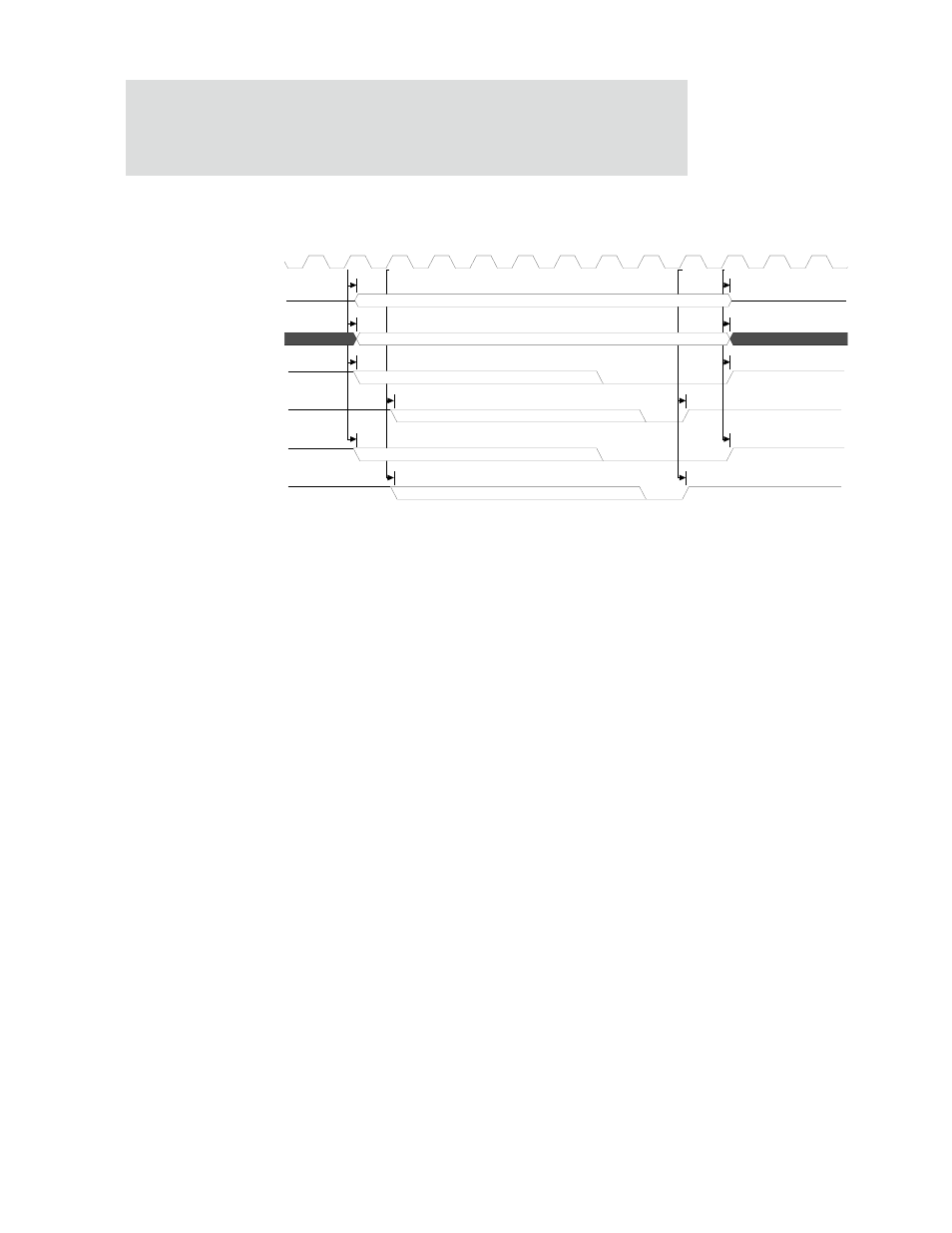
Static write cycle with configurable wait states
Figure 118: Static write cycle with configurable wait states
WTWR = from 0 to 15
WWEN = from 0 to 15
The WTWR field determines the length on the write cycle.
During a 32-bit transfer, all four
byte_lane
signals will go low.
During a 16-bit transfer, two
byte_lane
signals will go low.
During an 8-bit transfer, only one
byte_lane
signal will go low.
Notes:
1
Timing of the
st_cs_n
signal is determined with a combination of the WTWR and WWEN fields. The
st_cs_n
signal will always go low at least one clock before
we_n
goes low, and will go high one clock
after
we_n
goes high.
2
Timing of the
we_n
signal is determined with a combination of the WTWR and WWEN fields.
3
Timing of the
byte_lane
signals is determined with a combination of the WTWR and WWEN fields. The
byte_lane
signals will always go low one clock before
we_n
goes low, and will go one clock high after
we_n
goes high.
4
If the PB field is set to 0, the
byte_lane
signals will function as the write enable signals and the
we_n
signal will
always be high.
5
If the PB field is set to 0, the timing for the
byte_lane
signals is set with the WTWR and WWEN fields.
M22
M21
M24
M23
M22
M21
M20
M19
M18
M17
M16
M15
Note-2
Note-3
Note-5
Note-4
Note-1
CPU clock / 2
data<31:0>
addr<17:0>
st_cs_n<3:0>
we_n
byte_lane<3:0>
byte_lane[3:0] as WE*