Digi NS9750 User Manual
Page 192
D y n a m i c m e m o r y c o n t r o l l e r
1 6 8
N S 9 7 5 0 H a r d w a r e R e f e r e n c e
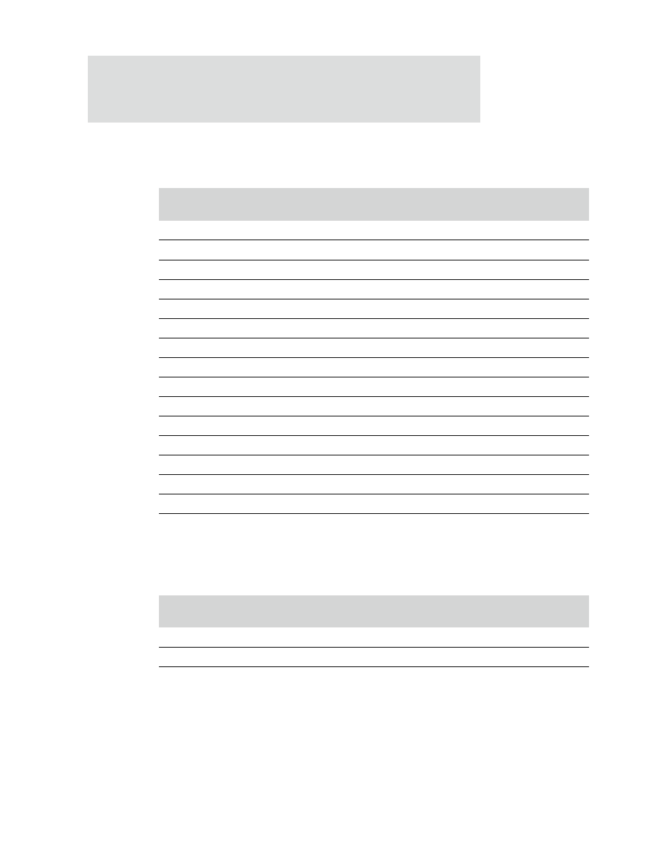
Table 95 shows the outputs from the memory controller and the corresponding inputs
to the 64 M SDRAM (8Mx8, pins 13 and 14 used as bank selects).
Table 96 shows the outputs from the memory controller and the corresponding inputs
to the 128M SDRAM (4Mx32, pins 13 and 14 used as bank selects).
Output address
(
ADDROUT
)
Memory device
connections
AHB address to row
address
AHB address to
column address
14
BA1
11
11
13
BA0
12
12
12
-
-
-
11
11
24
-
10
10/AP
23
AP
9
9
22
-
8
8
21
10
7
7
20
9
6
6
19
8
5
5
18
7
4
4
17
6
3
3
16
5
2
2
15
4
1
1
14
3
0
0
13
2
Table 95: Address mapping for 64M SDRAM (8Mx8, RBC)
Output address
(
ADDROUT
)
Memory device
connections
AHB address to row
address
AHB address to
column address
14
BA1
11
11
13
BA0
10
10
12
-
-
-
Table 96: Address mapping for 128M SDRAM (4Mx32, RBC)