Dma buffer descriptor – Digi NS9750 User Manual
Page 528
D M A b u f f e r d e s c r i p t o r
5 0 4
N S 9 7 5 0 H a r d w a r e R e f e r e n c e
DMA buffer descriptor
All DMA channels operate using a buffer descriptor. Each DMA channel remains idle
until enabled through the DMA Channel Control register. When a DMA channel is
activated, it reads the DMA buffer descriptor pointed to by the Buffer Descriptor
Pointer register. When the current descriptor is retired, the next descriptor is
accessed from a circular buffer.
Each DMA buffer descriptor is four 32-bit words in length. Multiple buffer descriptors
are located in circular buffers of 1024 bytes, with a maximum of 64 buffer
descriptors. The DMA channel’s buffer descriptor pointer provides the first buffer
descriptor address. Subsequent buffer descriptors are found adjacent to the first
descriptor. The final buffer descriptor is defined with its W bit set. When the DMA
channel encounters the W bit, the channel wraps around to the first descriptor.
Note:
Configuring a DMA channel for more than the maximum number of buffer
descriptors results in unpredictable behavior.
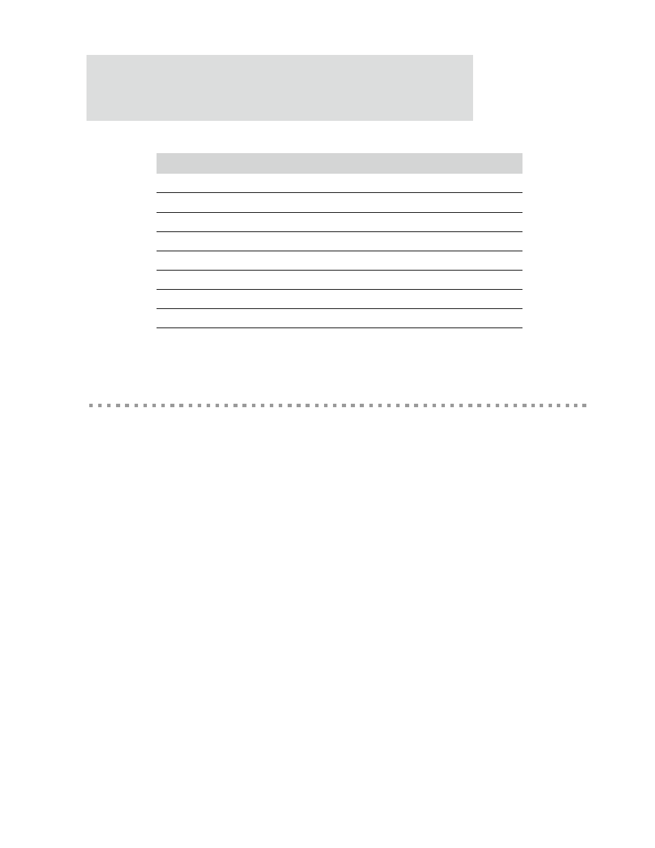
Figure 84 shows the DMA buffer descriptor. Table 303 explains each buffer descriptor
component.
Offset
Description
0x00
Buffer descriptor pointer
0x01
Control register
0x02
Status register
0x03
Unused
0x04
Source Address register
0x05
Buffer Length register
0x06
Destination Address register
0x07
Control flags and transfer status
Table 302: DMA context memory entry