Serial channel b/a/c/d control register a – Digi NS9750 User Manual
Page 676
S e r i a l p o r t c o n t r o l a n d s t a t u s r e g i s t e r s
6 5 2
N S 9 7 5 0 H a r d w a r e R e f e r e n c e
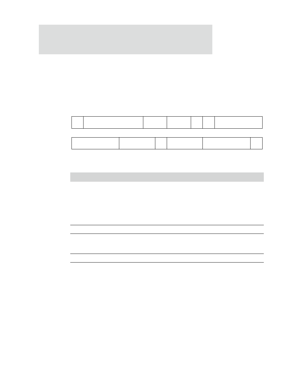
Serial Channel B/A/C/D Control Register A
Address: 9020 0000 / 0040
9030 0000 / 0040
There are two Serial Channel B/A/C/D Control Registers A within each two-channel
serial controller module.
Register bit assignment
Bits
Access
Mnemonic
Reset
Description
D31
R/W
CE
0
Channel enable
0
Resets the port and the data FIFOs (disables the
channel)
1
Enables a serial channel operation
The CE field cannot be set until all control bits in Serial
Channel Control Register A, Control Register B, and Bit-
rate register are stable.
D30:26
R/W
Not used
0
Always write as 0.
D25:24
R/W
WLS
00
Word length select
This value must be
2’b11
to select a word length of 8 data
bits. SPI mode requires this word length.
D23:22
R/W
Not used
Always write as 0.
D21
R/W
RL
0
Remote loopback
Provides a remote loopback feature.
When RL is set to 1, the TXD transmit output is connected
to the RXD receive input. The RL field immediately
echoes receive data back as transmit data.
This field is used primarily as a test vehicle for external
data equipment.
Table 384: Serial Channel B/A/C/D Control Register A
RIE
ERX
DMA
Reserved
TIC
ETX
DMA
13
12
11
10
9
8
7
6
5
4
3
2
1
0
15
14
31
29
28
27
26
25
24
23
22
21
20
19
18
17
16
30
RL
LL
Not used
CE
Not used
Not used
Not used
WLS