Serial channel b/a/c/d control register a – Digi NS9750 User Manual
Page 635
w w w . d i g i e m b e d d e d . c o m
6 1 1
S e r i a l C o n t r o l M o d u l e : U A R T
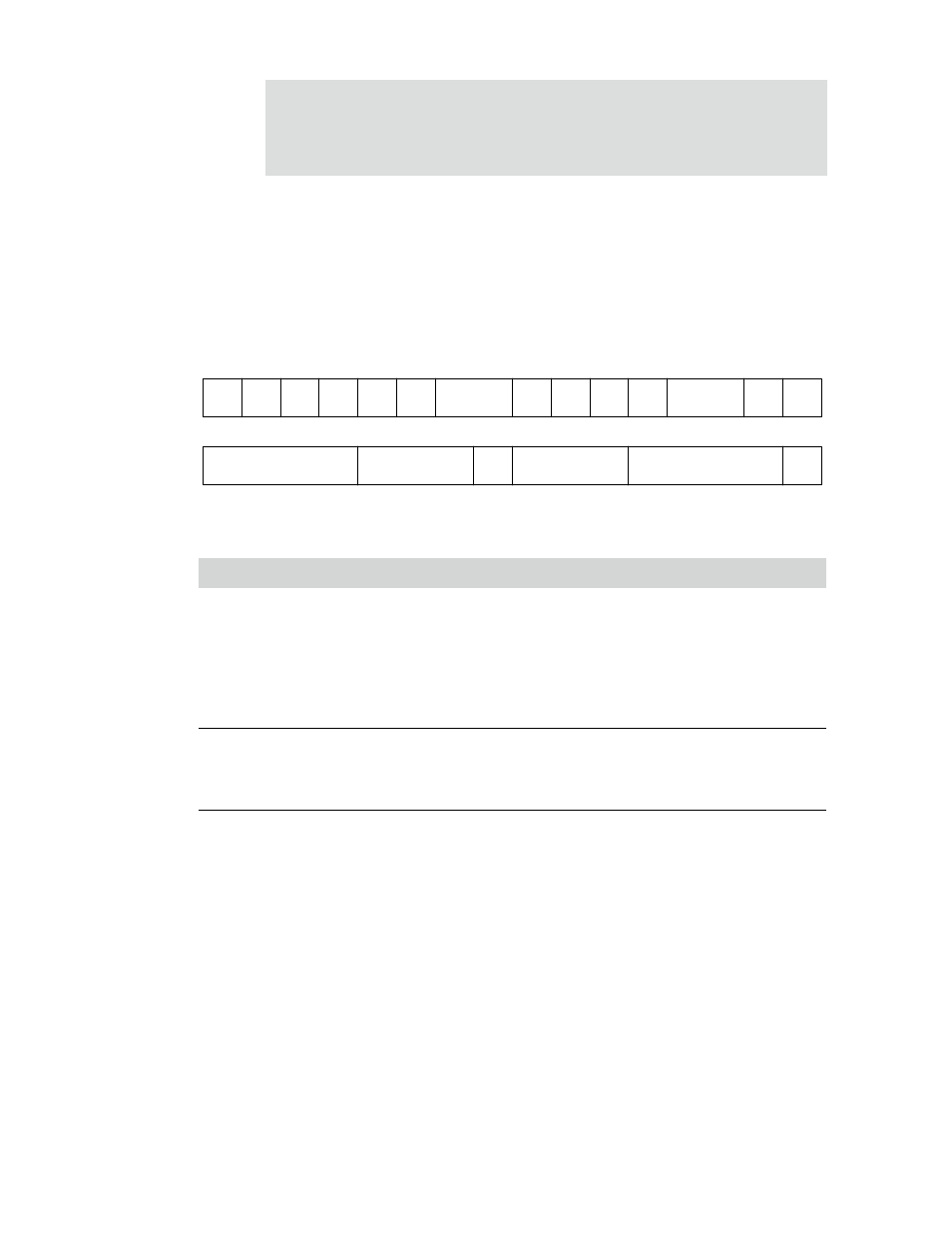
Serial Channel B/A/C/D Control Register A
Address: 9020 0000 / 0040
9030 0000 / 0040
There are two Serial Channel B/A/C/D Control Registers A within each two-channel
serial controller module.
Register bit assignment
Bits
Access
Mnemonic
Reset
Description
D31
R/W
CE
0
Channel enable
0
Resets the port and the data FIFOs (disables the
channel)
1
Enables a serial channel operation
The CE field must not be set until all control bits in Serial
Channel Control Register A, Control Register B, and Bit-
rate register have been defined.
D30
R/W
BRK
0
Send break
Forces a break condition in UART mode. While BRK is
set to 1, the UART transmitter outputs a logic 0 or a space
condition on the TXD output signal.
D29
R/W
STICKP
0
Stick parity
Can be used to force the UART parity field to a certain
state as defined by the EPS field (see D28), instead of a
parity bit calculated against the data word. STICKP
applies only when the PE field (see D27) is also set to 1.
Set STICKP to 1 to force transmission of the static parity
value.
Table 367: Serial Channel B/A/C/D Control Register A
RIE
ERX
DMA
RIC
TIC
ETX
DMA
13
12
11
10
9
8
7
6
5
4
3
2
1
0
15
14
31
29
28
27
26
25
24
23
22
21
20
19
18
17
16
30
STICK
P
EPS
STOP
PE
WLS
CTSTX RTSRX
RL
LL
Not used
DTR
RTS
CE
BRK
Not used