Digi NS9750 User Manual
Page 150
S t a t i c m e m o r y c o n t r o l l e r
1 2 6
N S 9 7 5 0 H a r d w a r e R e f e r e n c e
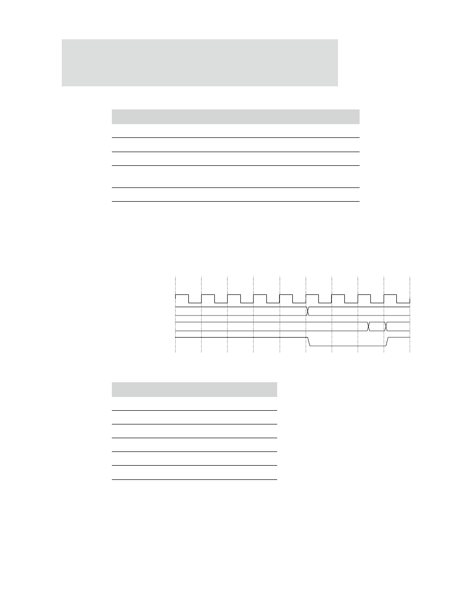
Figure 42 shows an external memory read transfer with two wait states (
WAITRD=2
).
Seven AHB cycles are required for the transfer, five for the standard read access and
an additional two because of the programmed wait states added (
WAITRD
). Table 51
provides the timing parameters. Table 52 describes the transactions in Figure 42.
Figure 42: External memory 2 wait state read timing diagram
Cycle
Description
T0
AHB address provided to memory controller.
T0-T1
AHB transaction processing.
T1-T4
Arbitration of AHB memory ports.
T4-T5
Static memory address, chip select, and control signals submitted to
static memory.
T5-T6
Read data returned from the static memory. Data is provided to AHB.
Table 50: External memory 0 wait state read
Timing parameter
Value
WAITRD
2
WAITOEN
0
WAITPAGE
N/A
WAITWR
N/A
WAITEN
N/A
WAITTURN
N/A
Table 51: Static memory timing parameters
STCSOUT_n
COEOUT_n
clk_out
ADDR
DATAIN
A
D(A)
T0
T1
T2
T3
T4
T5
T6
T7
T8