Ieee 1284 timing, Ieee 1284 timing example – Digi NS9750 User Manual
Page 855
w w w . d i g i e m b e d d e d . c o m
8 3 1
T i m i n g
IEEE 1284 timing
Note:
All AC characteristics are measured with 10pF, unless otherwise noted.
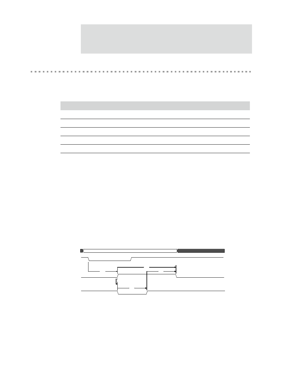
Table 476 describes the values shown in the IEEE 1284 timing diagram (Figure 140).
Notes:
1
The range is 0ns up to one time unit.
2
Two time units.
3
Three time units.
IEEE 1284 timing example
The IEEE 1284 timing is determined by the BBus clock and the Granularity Count
register (GCR) setting. In this example, the BBus clock is 50 MHz and the Granularity
Count register is set to 25. The basic time unit is
1/50 MHz x 25
, which is 500ns.
Figure 140: IEEE 1284 timing with BBus clock at 50 MHZ and GCR set to 25
Parm
Description
Min
Max
Unit
Note
IE1
Busy-while-Strobe
0
500
ns
1
IE2
Busy high to nAck low
0
ns
IE3
Busy high
1000
ns
2
IE4
nAck low
500
ns
3
IE5
nAck high to Busy low
500
ns
3
Table 476: IEEE 1284 timing parameters
IE1
IE3
IE5
IE2
IE4
Data[8:1]
nStrobe
Busy
nAck