Ethernet front-end module, Figure 65: ethernet front-end module block diagram – Digi NS9750 User Manual
Page 347
w w w . d i g i e m b e d d e d . c o m
3 2 3
E t h e r n e t C o m m u n i c a t i o n M o d u l e
Ethernet front-end module
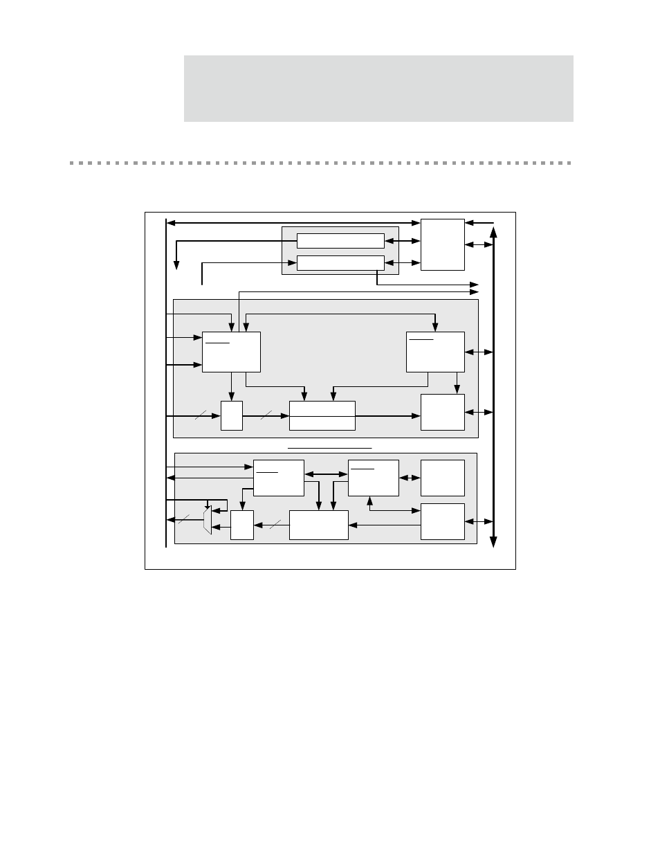
Figure 65 shows the Ethernet front-end module (EFE).
Figure 65: Ethernet front-end module block diagram
The EFE module includes a set of control and status registers, a receive packet
processor, and a transmit packet processor. On one side, the Ethernet front end
interfaces to the MAC and provides all control and status signals required by the MAC.
On the other side, the Ethernet front end interfaces to the system.
The receive packet processor accepts good Ethernet frames (for example, valid
checksum and size) from the Ethernet MAC and commits them to external system
TX FIFO
256 Bytes
AHB
TX
Master
Interface
Control Registers
Et
h
e
rn
e
t M
A
C
Tx Data
RD Data
WR Data
AH
B
AHB
Slave
Interface
TX_WR
-AHB User I/F
-FIFO WR Ctl
-RAM Ctl
TX_RD
-MAC TX Ctl
-FIFO RD Ctl
TX-Buffer
Descriptor
Ram
64 entries
32:8
8
32
Tx Ctl
Tx Status
WR Ctl
RX _RD
-AHB User I/F
-DMA Pointers
-FIFO RD Ctl
8:32
RX_WR
-Src Addr Filter
-FIFO WR Ctl
AHB
RX
Master
Interface
Rx Data
Rx Status
Rx Ctl
SAL Accept/Reject
Status Registers
MAC Host I/F, Stat Host I/F, SAL Host I/F
RX Interrupt, TX Interrupt
To Receive/Transmit
Packet Processors
8
32
Receive Packet Processor
Transmit Packet Processor
System Cfg
Rx_frame
SA and CTL
SA M
u
x
From Receive/Transmit Packet Processors
RX Data FIFO
2KB
RX Status FIFO
32 entry