Registers – Digi NS9750 User Manual
Page 603
w w w . d i g i e m b e d d e d . c o m
5 7 9
L C D C o n t r o l l e r
If you want reduced resolution, the least significant color bits can be dropped,
starting with Red[0], Green[0], and Blue[0].
Registers
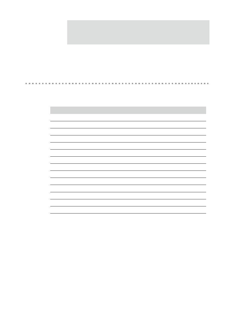
Table 349 lists the LCD controller registers. All configuration registers must be
accessed as 32-bit words and as single accesses only. Bursting is not allowed.
Address
Register
Description
A080 0000
LCDTiming0
Horizontal axis panel control
A080 0004
LCDTiming1
Vertical axis panel control
A080 0008
LCDTiming2
Clock and signal polarity control
A080 000C
LCDTiming3
Line end control
A080 0010
LCDUPBASE
Upper panel frame base address
A080 0014
LCDLPBASE
Lower panel frame base address
A080 0018
LCDINTRENABLE
Interrupt enable mask
A080 001C
LCDControl
LCD panel pixel parameters
A080 0020
LCDStatus
Raw interrupt status
A080 0024
LCDInterrupt
Final masked interrupts
A080 0028
LCDUPCURR
LCD upper panel current address value
A080 002C
LCDLPCURR
LCD lower panel current address value
A080 0030 – A080 01FC
Reserved
Reserved
A080 0200 – A080 03FC
LCDPalette
256 x 16-bit color palette
Table 349: LCD registers