Yokogawa Data Acquisition with PID Control CX2000 User Manual
Page 91
1-79
IM 04L31A01-01E
Explanation of Functions
3
2
1
4
5
6
7
8
9
10
11
12
13
14
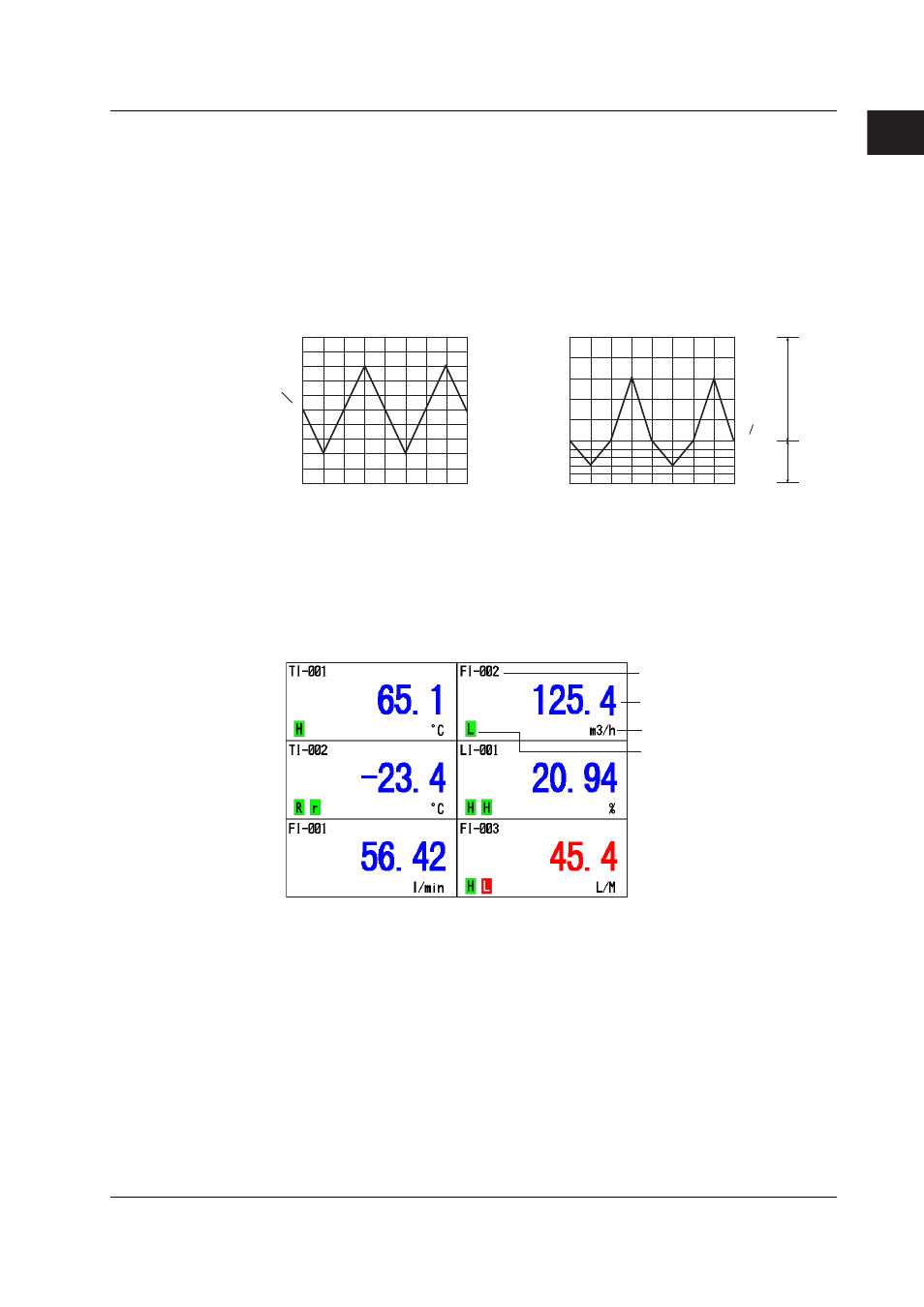
Partial Expanded Display
This function compresses a section of the waveform display range and expands the rest
of the section. In this function, you specify the destination position (the new boundary
position) where a single value (boundary point) in the display range is moved. In the
example in the figure, 0 V (boundary value) is moved to the 30% position of the display
range (new boundary position). The 30% below the boundary corresponds to “–6 V to 0
V” and 70% above the boundary corresponds to “0 V to 6 V.”
100
Percentage with
respect to the
display span
Measured
value
Boundary
New
boundary
position
100
30
0
50
0
6V
0
–6V
–6V
0
Expanded section
Reduced
section
Time axis
Time axis
When partial expanded display is used
When partial expanded display is not used
Measured
value
6V
Percentage with
respect to the
display span
Waveform color and line thickness
The waveform color can be set or changed for each channel. The waveform color and
the bar color in the bar graph display are the same.
You can select the thickness of the waveform line from 1 to 3 dots. The thickness of the
line cannot be set separately for each channel.
Control Operation Display > Digital Display
Displays the measured, computed, and control data numerically using large numbers.
Unit
Channel No. or tag name
Measured or computed value
Specified alarm
Updating of the Numerical Display
Measured/computed values are updated every second (every 2 s if the scan interval is
set to 2 s).
1.16 Display Function