Yokogawa Data Acquisition with PID Control CX2000 User Manual
Page 124
2-7
IM 04L31A01-01E
Installation and Wiring
3
2
1
4
5
6
7
8
9
10
11
12
13
14
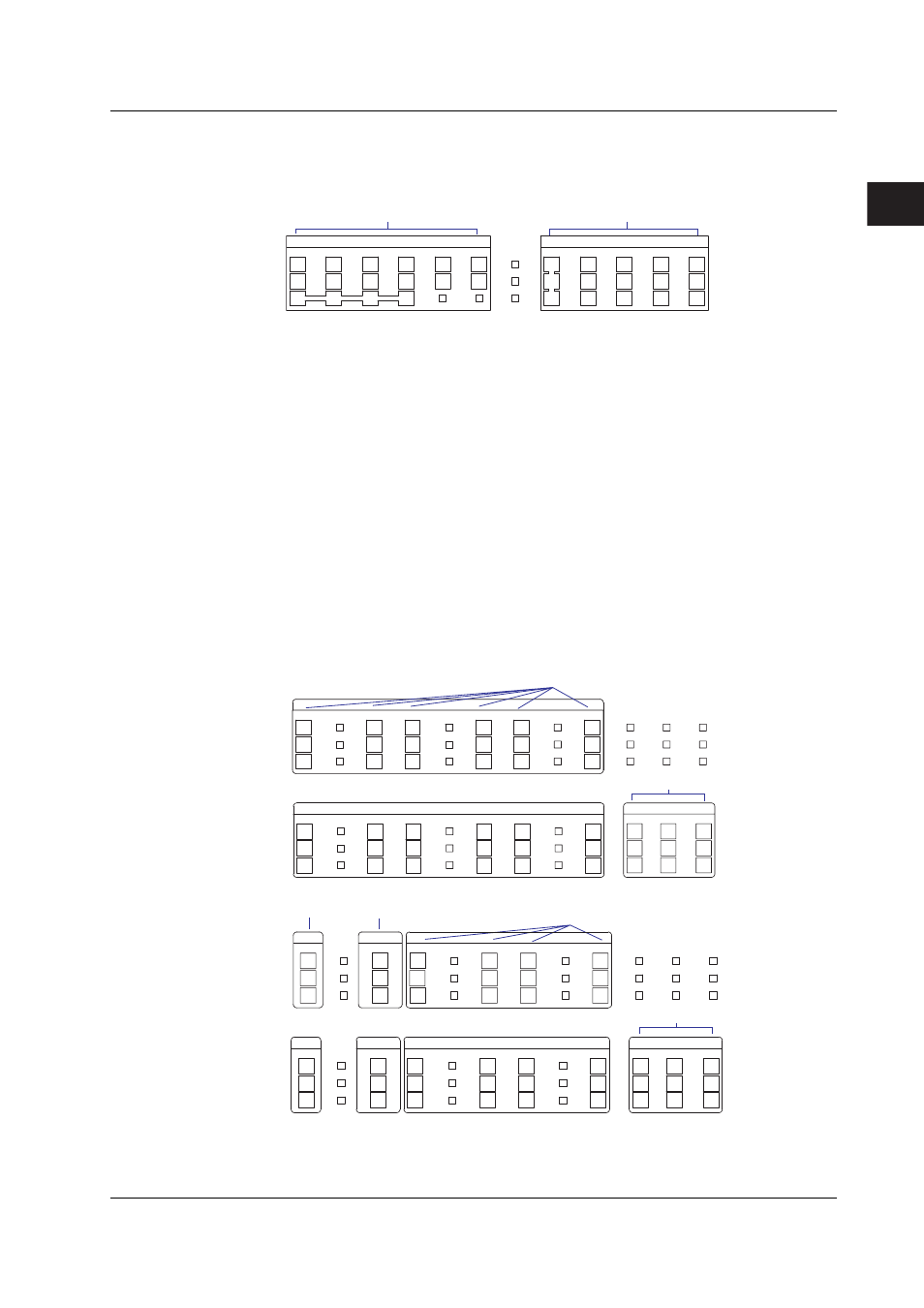
Terminal Arrangements of the Control DIO Expansion Terminal Block (Option
Terminal Block Provided with the /CST1 Option)
12 contact input and 12 transistor contact output terminals are arranged as shown in the
following figure. Wire the terminals according to the configuration.
DIGITAL OUT
11
12
C
10
11
12
C
C
C
9
10
C
7
8
C
5
6
3
4
1
2
5
6
3
4
8
9
7
1
2
C
DIGITAL IN
Transistor output
Contact input
C: Common
DIGITAL OUT terminals 1 to 12 are indicated using the following numbers when the
control DIO expansion terminal block EXTDIO is selected in the contact (relay) output
registration setting.
RO001 to RO012
In addition, DIGITAL IN terminals 1 to 12 are indicated using the following numbers when
the control DIO expansion terminal block EXTDIO is selected in the contact input
registration setting.
RI001 to RI012
Terminal Arrangements of the Measurement Alarm Option Terminal Block
The measurement alarm option terminal block is the terminal block that you specified as
an option at the time of purchase. The following four types are available.
/A6:
6 measurement alarm outputs
/A6R:
6 measurement alarm outputs and 8 measurement remote inputs
/A4F:
4 measurement alarm outputs, 1 FAIL output, and 1 memory end output
/A4FR: 4 measurement alarm outputs, 1 FAIL output, 1 memory end output, and 8
measurement remote inputs.
The following figure shows the terminal arrangements on each measurement alarm
option terminal block. Wire the terminals according to the configuration.
ALARM
06
NC
NO
C
05
NC
NO
C
04
NC
NO
C
03
NC
NO
C
02
NC
NO
C
01
NC
NO
C
ALARM
REMOTE
06
NC
NO
C
05
NC
NO
C
04
NC
NO
C
03
NC
NO
C
02
NC
NO
C
01
6
7
8
3
4
5
C
1
2
NC
NO
C
Alarm output
• /A6 option
Measurement remote input
• /A6R option
C: Common
NO: Normally Opened
NC: Normally Closed
Alarm output
• /A4F option
Measurement remote input
• /A4FR option
C: Common
NO: Normally Opened
NC: Normally Closed
ALARM
REMOTE
01
02
03
04
FAIL
ALARM
MEMORY
MEMORY
02
01
03
04
FAIL
C
1
2
3
4
5
6
7
8
NC
NO
C
NC
NO
C
NC
NO
C
NC
NO
C
NC
NO
C
NC
NO
C
NC
NO
C
NC
NO
C
NC
NO
C
NC
NO
C
NC
NO
C
NC
NO
C
Memory end output
FAIL output
ALARM terminals 01 to 06 are indicated using [I01] to [I06] in the measurement alarm
output settings (see section 7.2, “Setting Related to Measurement alarm ”).
REMOTE terminals 1 to 8 are indicated using numbers 1 to 8 in the measurement
remote output settings (see section 11.5, “Setting the Measurement Remote Input”).
2.3 Wiring