13 measurement function overview, Measurement function overview -58 – Yokogawa Data Acquisition with PID Control CX2000 User Manual
Page 70
1-58
IM 04L31A01-01E
1.13 Measurement Function Overview
Measurement Input
DC voltage, thermocouple, resistance temperature detector, or ON/OFF signal (contact
signal or voltage signal) can be measured. The input signal is A/D-converted at a scan
interval of 1 s or 2 s and acquired to the internal memory. In addition, difference
computation, square-root computation, and scaling can be carried out on the measured
data and acquired to the internal memory.
Displaying the Measured Data
The measured data acquired to the internal memory can be displayed on the operation
display using trend waveforms, numeric values (digital values), or bar graphs.
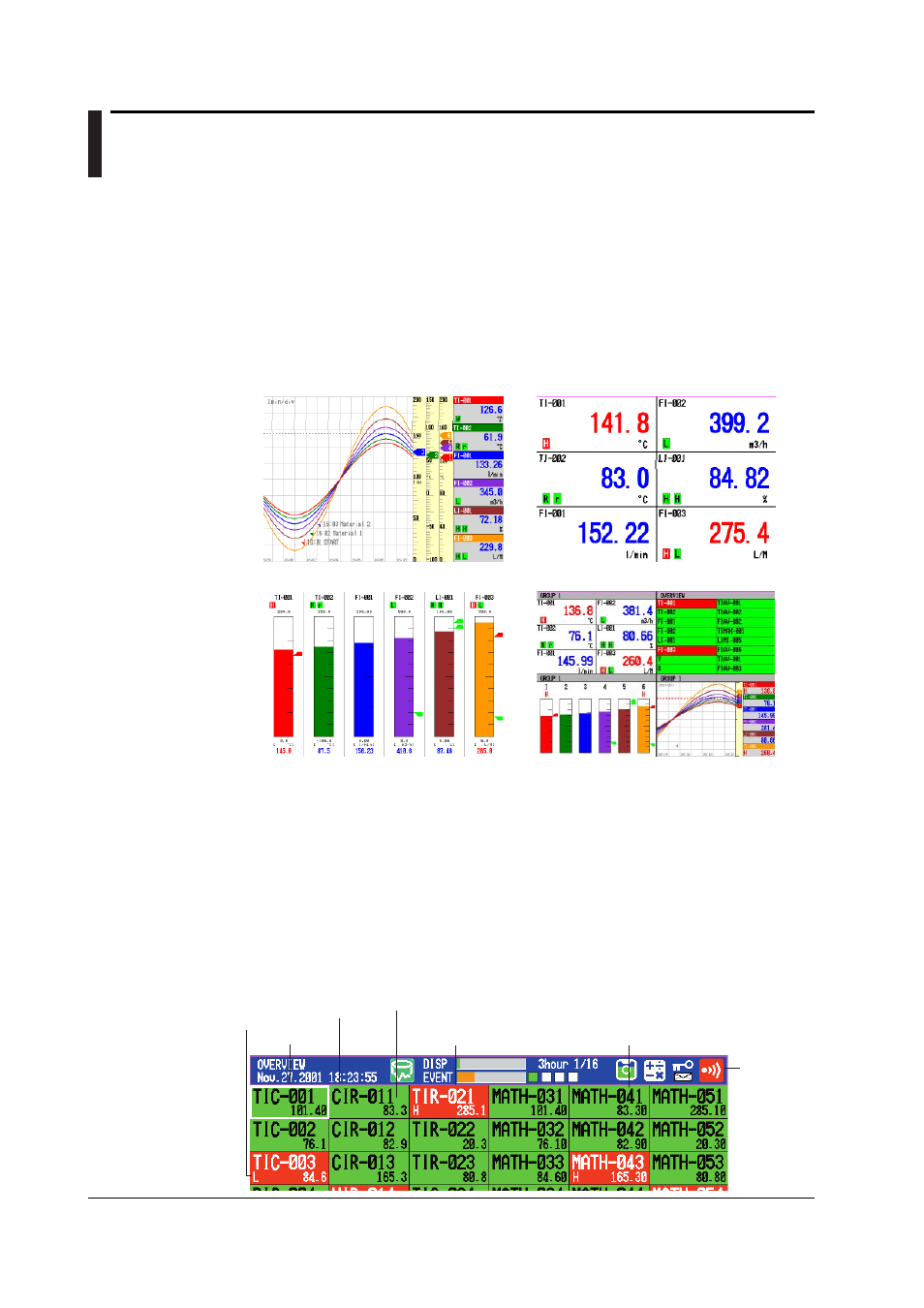
Trend Display
Digital Display
Bar Graph Display
4 Screen Display
Measurement Alarms
Alarms can be generated when the measured/computed data meets a certain condition.
When an alarm occurs, you can have the information about the alarm displayed on the
operation display. Also, you can output relay signals from the alarm output terminal
(ALARM) on the measurement alarm option terminal block, the control output terminal
block, the relay contact output on the control DIO expansion terminal block, or the
transistor output terminal (DIGITAL OUT). You can also turn the internal switches ON.
On the operation display, the alarm status is displayed as alarm icons in the status
display section and using methods such as the trend, digital, bar graph, overview
displays. The detailed information about the alarms is displayed in the alarm summary.
Alarm Indication Example on the Overview Display
Cursor
Area of channels on which an
alarm is occurring is indicated
in red
Area of channels on which an alarm
is not occurring is indicated in green
Measured value or
computed value
Channel No.
or tag name
Alarm type
Alarm icon