Yokogawa Data Acquisition with PID Control CX2000 User Manual
Page 29
1-17
IM 04L31A01-01E
Explanation of Functions
3
2
1
4
5
6
7
8
9
10
11
12
13
14
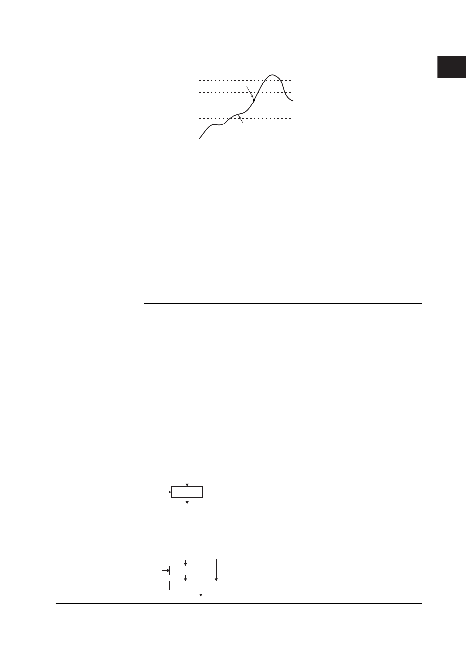
No.1 PID
Reference point 1
Reference point 2
Reference point 3
Reference point 4
Reference point 5
No.2 PID
No.3 PID
No.4 PID
No.5 PID
No.6 PID
Maximum value of
measurement span
Minimum value of
measurement span
Change in the
PV.
If the current PV here,
control using thePID
constant of No. 4.
Restart and Restart for Program Control
Select how the CX2000 is to behave when an extended power failure occurs during control
operation (power failure period of 5 s or more) and the power recovers.
• Continue (initial setting):
Continue the operation before the power failure occurred.
• Manual operation:
Start from the manual operation condition.
• Auto operation (only during fixed-point operation):
Auto operation by continuing the operation before the power failure occurred.
• Reset (only during program operation):
Stop the program operation.
Note
If the duration of the power failure is less than or equal to 2 s (a short power disruption), the
operation before the disruption continues. If the duration is between 2 to 5 s, the behavior for a
short power disruption or an extended power failure is carried out depending on the condition.
Initial PID
Select whether the initial PID constant in PID parameter settings (see page 1-32) is
optimized to temperature control, pressure control, or flow control. Below are the initial
values of PID constants.
Initial values for temperature: P = 5.0%, I = 240 s, and D = 60 s.
Initial values for pressure/flow: P = 120.0%, I = 20 s, and D = 0 s.
6/4 Loop Select (only on 6-loop models)
Select whether the number of loops used is 6 (factory default setting) or 4. If set to 6
loops, a limitation occurs in the assignment of analog control input signal (see
“Difference in the Control Input Configuration According to the 6/4 Loop Selection and
Control Mode” on the next page).
Control Mode
The following three control modes are available. The mode is selected for each control loop.
• Single-loop control
Basic control consisting of a single system of controller CPU.
PID
SP
PV
OUT
• Cascade control
Control consisting of two systems of controller CPUs that uses the primary control
output as the secondary control SP. Continuous PID control is only possible for
primary control.
PID
SP
PV1
PV2
PID
OUT
1.3 Basic Settings of Control