Caution – Yokogawa Data Acquisition with PID Control CX2000 User Manual
Page 120
2-3
IM 04L31A01-01E
Installation and Wiring
3
2
1
4
5
6
7
8
9
10
11
12
13
14
Installation Procedure
Use a 2 mm to 26 mm thick steel plate for the panel on which the CX2000 is to be
mounted.
1. Insert CX2000 from the front of the panel.
2. Using the mounting brackets that came with the package, insert the CX2000 to the
panel as shown in the following figure.
• Two mounting brackets are used at the top and bottom or left and right of the case
(remove the seal that is covering the holes of the mounting brackets on the case
beforehand).
• The adequate tightening torque of the screws for the panel mounting brackets is
0.7 to 0.9 N·m.
• Mount the CX2000 to the panel according to the procedure below.
• First, attach the two mounting brackets and temporarily fasten the attachment
screws.
• Next, fix the CX in place by tightening the attachment screws with the
appropriate torque. When the CX is approximately perpendicular to the panel as
you fasten the screws, press the mounting bracket against the case so that they
are in contact with each other.
CAUTION
Tightening the screws with a torque greater than the adequate tightening torque
can cause deformation of the case or damage to the bracket.
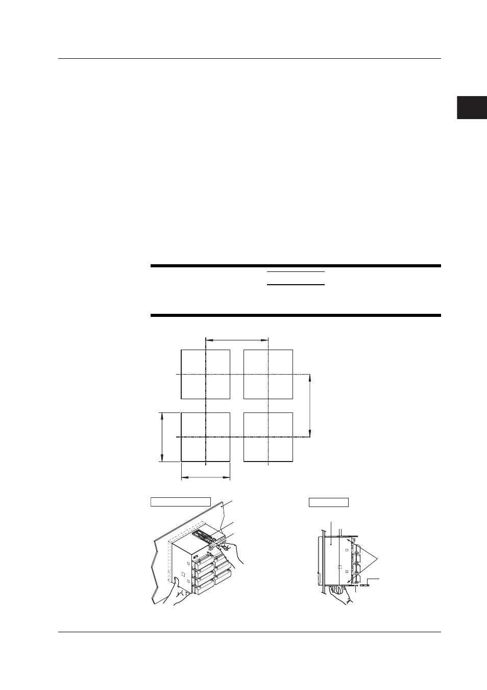
Panel Cut Diagram
361 min.
360 min.
281
+2
0
281
+2 0
Unit: mm
Panel Mounting Diagram
(The figure shows the case when the mounting
brackets are used on the top and bottom of the case.)
Screw temporarily
Fix in place
Front
Panel
Panel
Mounting bracket
Mounting bracket
Torque driver
(flat blade)
Attachment screw
Case
In contact
with each other
Attachment screw
2.2 Installation