Control output (loop1 to 6) wiring, Contact output (digital out) wiring – Yokogawa Data Acquisition with PID Control CX2000 User Manual
Page 137
2-20
IM 04L31A01-01E
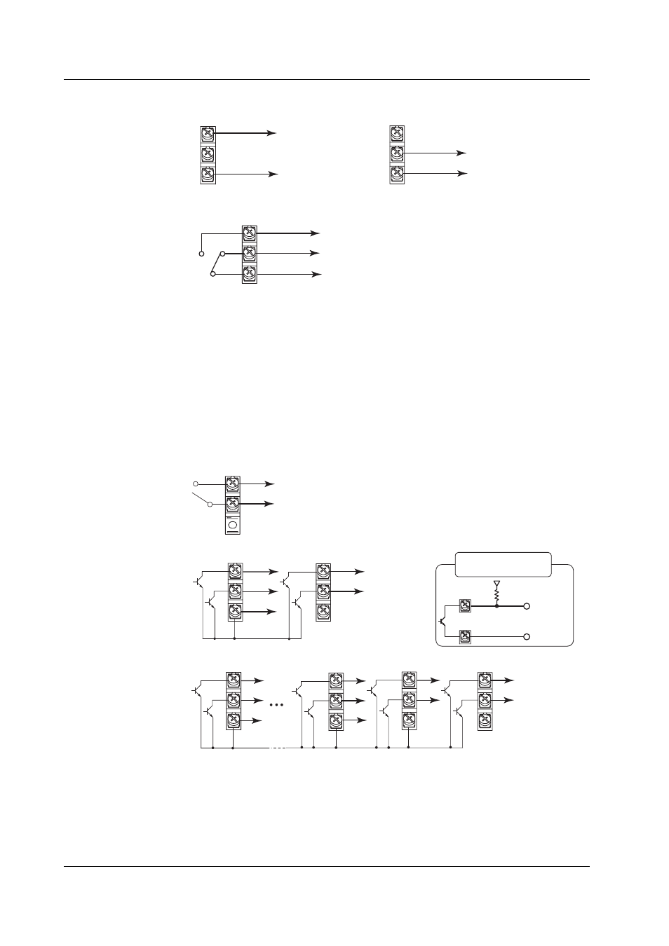
Control Output (LOOP1 to 6) Wiring
C
mA
+
–
4 to 20 mADC or
0 to 20 mADC
Voltage pulse output
Current output
Relay contact output
C
PULS
250 VAC, 3 A or
30 VDC, 3 A
(resistive load)
Voltage pulse (12 V)
(when set to energized)
+
–
NC
C
NO
Current Output Specifications
Output signal:
4 to 20 mADC or 0 to 20 mADC
Load resistance: 600 Ω or less
Voltage Pulse Output Specifications
Output signal:
ON voltage = 12 VDC
Load resistance: 600 Ω or more
Relay Contact Output Specifications
Output signal:
NC, NO, COM
Contact rating:
250 VAC (50/60 Hz)/3 A or 30 VDC/3 A (resistive load)
Contact Output (DIGITAL OUT) Wiring
Relay contact output of the control output terminal block
C
NO
250 VAC, 1 A or
30 VDC, 1 A
(resistive load)
Transistor output of the control output terminal block
C
6
5
4
3
24 VDC/50 mA
Transistor output of the control expansion DIO terminal block
4
3
2
1
24 VDC/50 mA
6
5
C
C
12
11
C
3 to 6
1 to 12
+
−
Pull-up resistor
Connection example
for a transistor output
Relay Output Specifications
Output format:
Relay contact
Contact rating:
250 VAC (50/60 Hz)/1 A or 30 VDC/1 A (resistive load)
Transistor Output Specifications
Output format:
Open collector output
Contact rating:
24 VDC/50 mA
2.3 Wiring