Yokogawa Data Acquisition with PID Control CX2000 User Manual
Page 43
1-31
IM 04L31A01-01E
Explanation of Functions
3
2
1
4
5
6
7
8
9
10
11
12
13
14
Setpoint Limiter
This function is used to limit the range in which the SP is to change. The value is
specified using EU (0.0% to 100.0%). For a definition of the engineering unit (EUS), see
appendix 8, “Explanation of Engineering Units (EU and EUS).”
When not in program operation: Limit the change in the SP.
When in program operation: Limit the program setpoint.
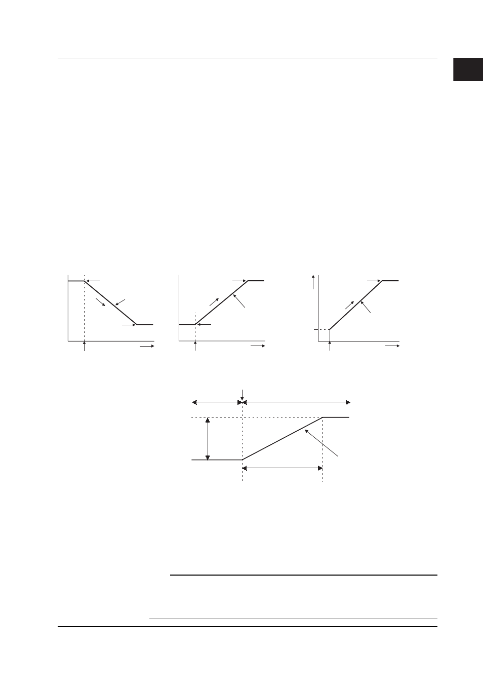
Ramp-rate Setting during Target Setpoint Switching
When you do not want the SP to change rapidly or when you wish to change the SP at a
constant velocity ramp-rate, you can set the velocity ramp-rate (target setpoint ramp-up
rate or target setpoint ramp-down rate) for raising or lowering the SP. The specified
velocity ramp-rate functions in the following cases.
• When the SP is changed.
• When the SP number is changed.
• When the CX2000 is powered up (or recovers after a power failure).
The SP changes according to the specified ramp-rate from the PV to the SP.
• When the CX2000 is switched from manual operation to auto operation.
The SP changes according to the specified ramp-rate from the PV to the SP.
Input rang
e
• When the SP is changed
SP (old)
Preset ramp-rate
SP (new)
SP change
Time
Time
Time
• When the SP number is changed
SP 2
Preset ramp-rate
SP 1
SP switching
Preset ramp-rate
• At the time of power-up (or recovery
after power failure) or when manual/auto
operation is switched
SP
PV
Power-up or manual/auto switching
The following figure shows an example in which the ramp-up rate is set to 70 (°C/minute)
and the CX2000 is operating at SP 1 = 500 °C and a switch is made to SP 2 = 640 °C.
70°C/minute
Temperature rise time:
2 minutes
SP 1
SP 2 = 640°C
SP1 = 500°C
SP switching
Temperature difference:
140°C
SP 2
RSP Input
In addition to the value specified on the CX2000, the value determined from the analog
signal that is input to the RSP terminal of the control input terminal block can be used as the
SP. The input setting for the remote input analog signal is carried out in the same fashion as
the input setting for the PV input (see section 1.4, “PV Input Related Settings”). When using
the SP of the remote input, select [REMOTE] through the local/remote switching operation
(see page 6-4) on the operation display. The switching operation can also be carried out
using the contact input (see section 1.5, “Contact Input/Output Related Settings”).
Note
The remote input function can be used only when program control is not used. To use this
function, the program control ON/OFF setting (setting available only on models with the
program control option) must be set to [OFF] and “[Basic Control Settings] > [Contact Input
Registration] > [Remote Input Selection]” must be set to [REMOTE].
1.6 Target Setpoint Related Settings