Setting the alarm value, Alarm stand-by action, Alarm hysteresis – Yokogawa Data Acquisition with PID Control CX2000 User Manual
Page 52
1-40
IM 04L31A01-01E
Setting the Alarm Value
An alarm is registered for each SP of a single control loop. If the SP number (1 to 8) is
switched, the alarm value switches accordingly. Since up to 4 alarm types can be
assigned for each control loop, four alarm values can be assigned per SP number. You
can set the alarm value in the following range.
PV high/low limits, SP high/low limits: EU (0 to 100%) of the measurement span.
Deviation high/low limits: EUS (–100 to 100%) of the measurement span.
Deviation high & low limit, deviation within high & low limits: EUS (0 to 100%) of the
measurement span
Output high/low limit: –5.0 to 105.0%
Note
The alarm number corresponds to the SP number. If you change the SP number, the alarm
switches to the value of the corresponding alarm number.
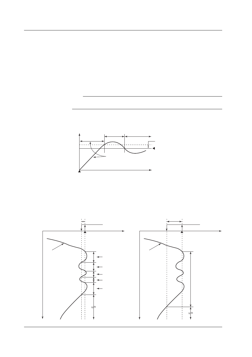
Alarm Stand-by Action
When the PV input reaches the SP at the initial stages of control operation, you can put
the alarm output on standby.
Normal
handling
PV
Power up
Time
Alarm is not output during
this period even if thePV is
below the alarm lower limit.
Alarm lower limit value
Normal
Failure
Alarm output
ON
Hysteresis
Alarm Hysteresis
The alarm hysteresis can be set in the range of EUS (0.0% to 10.0%) of the measurement span.
Below is an example of setting the hysteresis of alarm 1 when the alarm 1 type is set to
PV high limit. Open and close in the figure indicate the relay contact status. If the alarm
switching (ON/OFF) is excessive, the alarm hysteresis can be widened to lessen the
excessiveness. In the right figure, the switching of the alarm (ON/OFF) is slow because
the hysteresis width has been widened.
HY1: 15.0°C (example)
HY1: 5.0°C (example)
PV
Alarm ON
OFF
ON
OFF
ON
OFF
Alarm ON
OFF
Open
Open
Time
Time
Close (ON)
Close (ON)
AL 1 setpoint: 100.0°C
(example)
AL 1 setpoint: 100.0°C
(example)
PV
1.10 Control Alarm Related Settings