Fail output/self diagnosis output, Control operation mode – Yokogawa Data Acquisition with PID Control CX2000 User Manual
Page 18
1-6
IM 04L31A01-01E
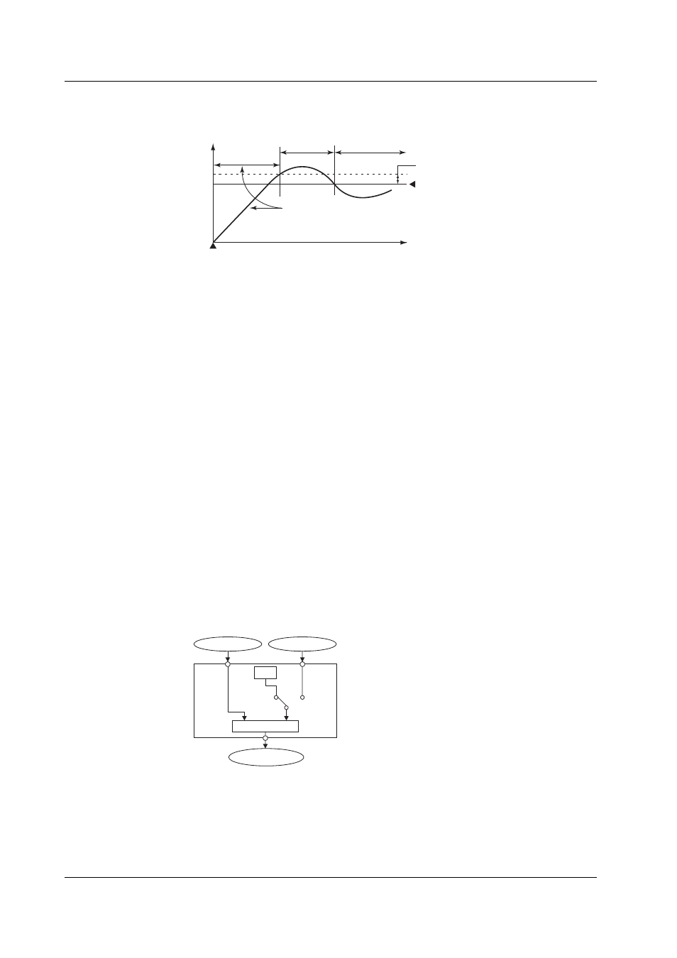
Alarm Standby
You can put the alarm output on standby at the initial stage of control operation until the
PV input reaches the SP.
Normal
handling
PV
Power up
Time
Alarm is not output during this
period even if the PV is below
the alarm low limit.
Alarm low limit value
Normal
Failure
Alarm output ON
Hysteresis
Alarm Mode
You can set the condition for disabling the alarm output (such as when the operation is stopped).
FAIL Output/Self Diagnosis Output
In addition to the alarm output described above, the following relay contact signal for
failure detection can be output from the control output terminal block.
• FAIL output
Output when a failure is detected in the CX2000 CPU. When a failure is detected, the
CX2000 is put in the following condition.
Control: Stopped (preset output if in the middle of operation, control output is off or
0% when power is turned ON)
• Self diagnosis output
Output when an input burnout, A/D converter failure, or RJC failure occurs. If an input
burnout or A/D converter failure is detected, the control output is set to the preset
output value. For RJC, PID control continues as though RJC is 0 °C.
Control Operation Mode
The following control operation switching is available. The control operation can be
switched using keys on the CX2000 control group display (see page 1-12), using contact
inputs, or via communications. For a description of the control operation modes on
models with the program control option, see “Program Control” in the next section. The
control function block diagram in the explanation below is a simplified one. For a
detailed control function block diagram for each control mode, see appendix 7.
Switching between Remote (REM) and Local (LOC)
Select whether control is executed using the SPs set on the CX2000 or using the
external analog signal (RSP) as the SP.
SP
Controller CPU
PV input
RSP input
(Analog signal)
Control output
Remote
(REM)
Local
(LOC)
PV
RSP
OUT
Switching between Auto (AUT), Manual (MAN), and Cascade (CAS)
When set to auto, the control output value (OUT) is computed from the deviation
between the PV input and the SP. When set to manual, the control output value (OUT)
that is set manually is used rather than the computed control output value (OUT).
Switching to “cascade (CAS)” is possible only when the control mode is set to “cascade
control.” In cascade control, the primary PID control output is used as the SP of the
secondary PID control.
1.2 Control Function Overview