Terminal cover labels, For the control dio expansion terminal block, 3 wiring – Yokogawa Data Acquisition with PID Control CX2000 User Manual
Page 125
2-8
IM 04L31A01-01E
Note
•
There are no output registration settings for the FAIL and MEMORY terminals. However,
the setting for outputting memory end, Memory Alarm Time, exists. In addition, FAIL
output can be assigned to the DIGITAL OUT1 terminal of the loop 1 and 2 control output
terminal block. In this case, registration settings are required.
•
The control alarm output cannot be assigned to the [ALARM] terminal. The control alarm
output can be assigned to the DIGITAL OUT terminal of the control output terminal block
and the control extension DIO terminal block. The measurement alarm output can be
assigned to the DIGITAL OUT terminal of the control output terminal block and the control
extension DIO terminal block.
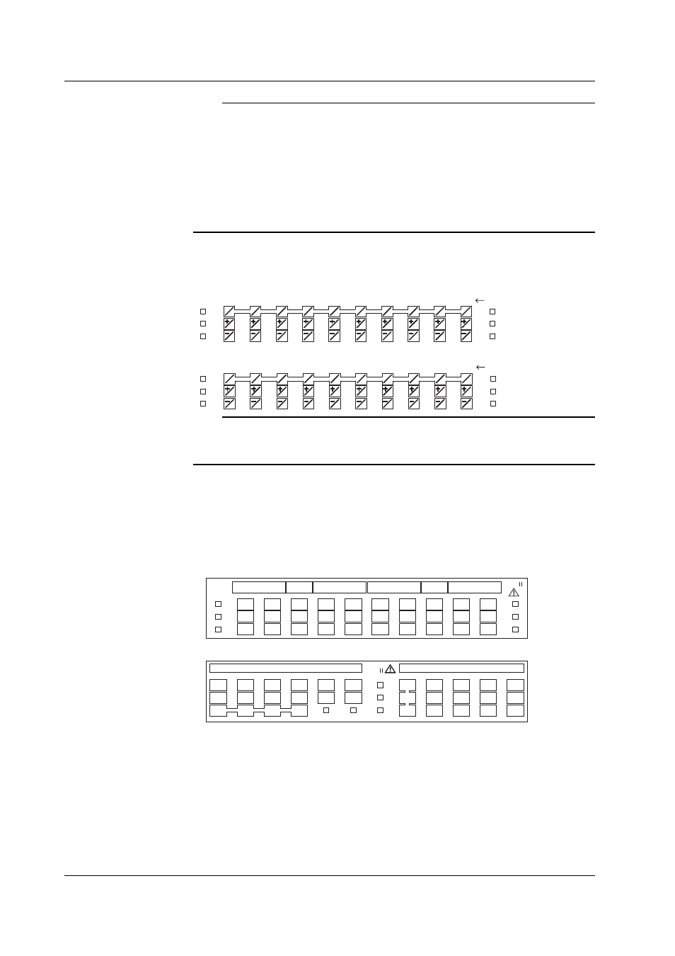
Terminal Arrangements of the Measurement Input Terminal Block
Ten measurement input terminals are available on each terminal block as shown in the
following figure.
• For CH1 to 10
b
A
B
1
b
A
B
2
b
A
B
3
b
A
B
4
b
A
B
5
b
A
B
6
b
A
B
7
b
A
B
8
b
A
B
9
b
A
B
10
Channel number
• For CH11 to 20
b
A
B
11
b
A
B
12
b
A
B
13
b
A
B
14
b
A
B
15
b
A
B
16
b
A
B
17
b
A
B
18
b
A
B
19
b
A
B
20
Channel number
Note
In the terminal arrangement diagram of the standard terminal block shown above, b terminals
are shorted with each other. If you specified the three-wire isolated RTD (/N2) option, b
terminals are isolated with each other.
Terminal Cover Labels
A label showing the arrangement of the terminals is affixed to the front and back of the
terminal cover of each terminal block.
Label on the Front of the Terminal Cover
The terminal numbers for checking the connection (not the numbers used in the settings)
are written on the label on the front of the terminal cover (see the following figure).
• For the 6 loop analog control input terminal block
LOOP5
004
005
006
007
008
009
010
011
012
013
014
015
016
017
018
019
020
021
022
023
024
025
026
027
028
029
030
031
032
033
LOOP1
LOOP4
LOOP2
LOOP3
LOOP6
CAT
• For the control DIO expansion terminal block
CAT
D I G I T A L I N
604
605
606
601
602
603
607
608
609
610
611
612
619
620
622
623
625
626
628
629
631
632
634
635
D I G I T A L O U T
613
614
615
636
633
630
627
2.3 Wiring